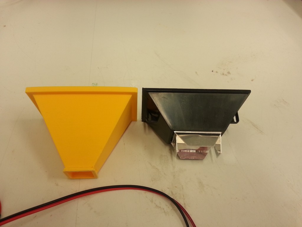
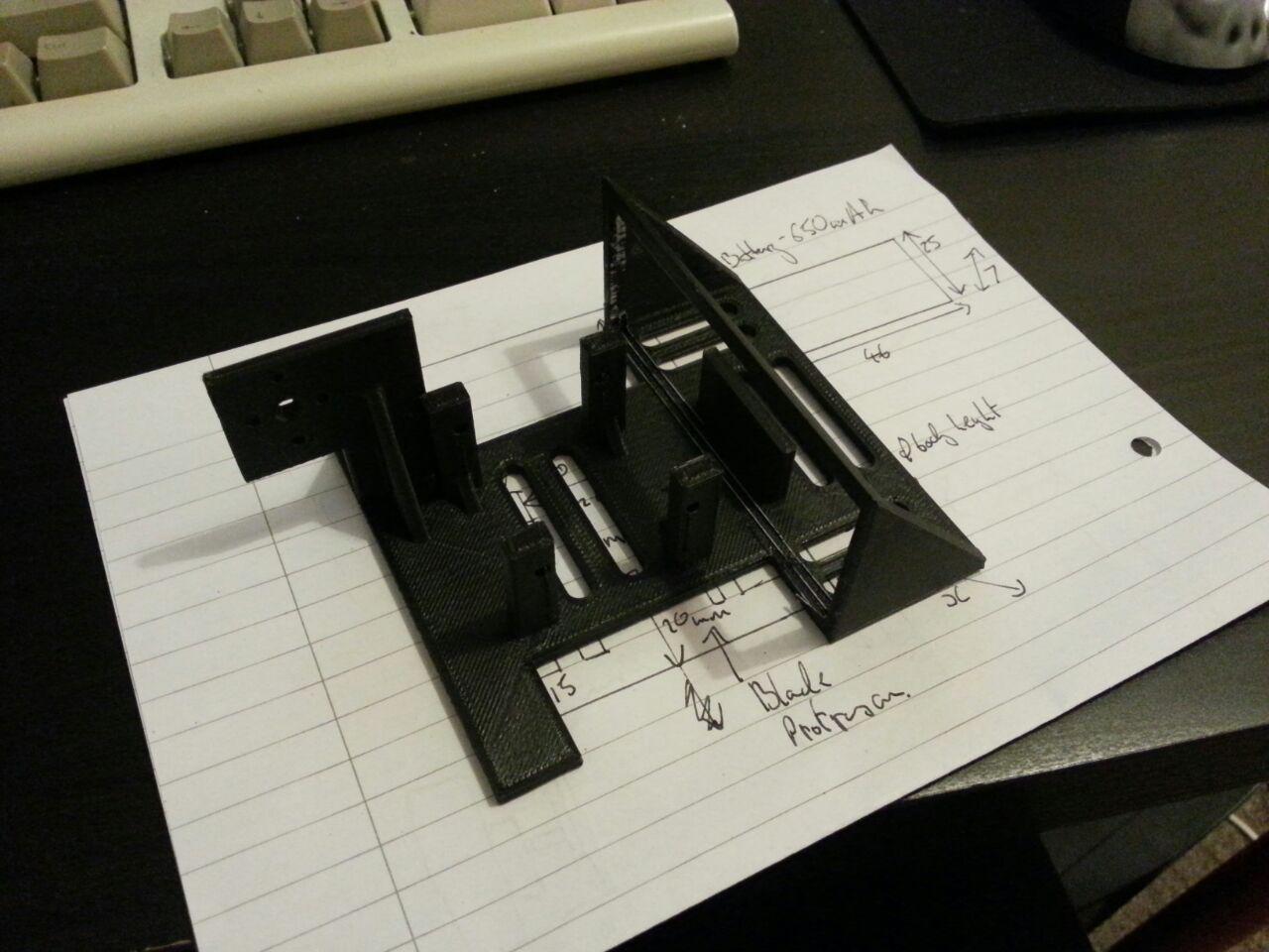
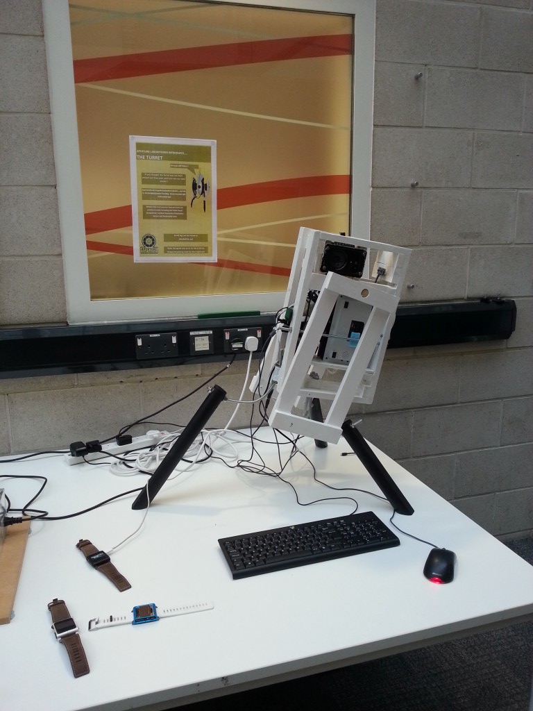
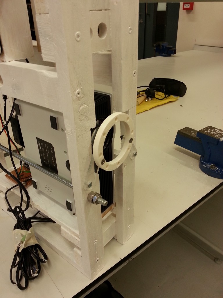
Here is a brief update on the portal turret. I’ve talked about it at each open day but I’ve finally designed and 3d printed a reflector that matches the new LED array to the Fresnel lens and LCD.
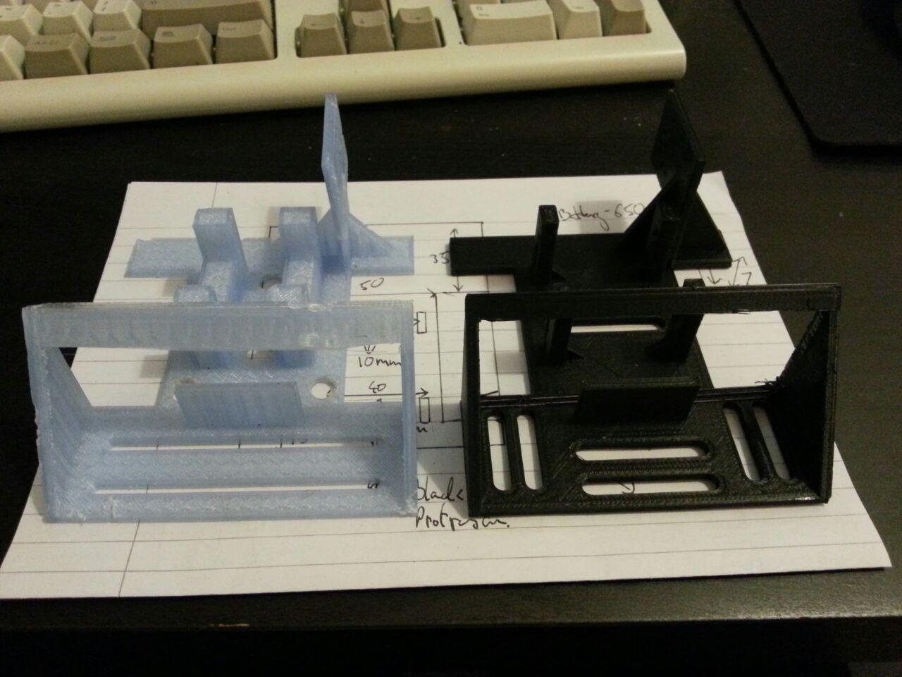
Side by side you can see the extra length required match up with the new LED.
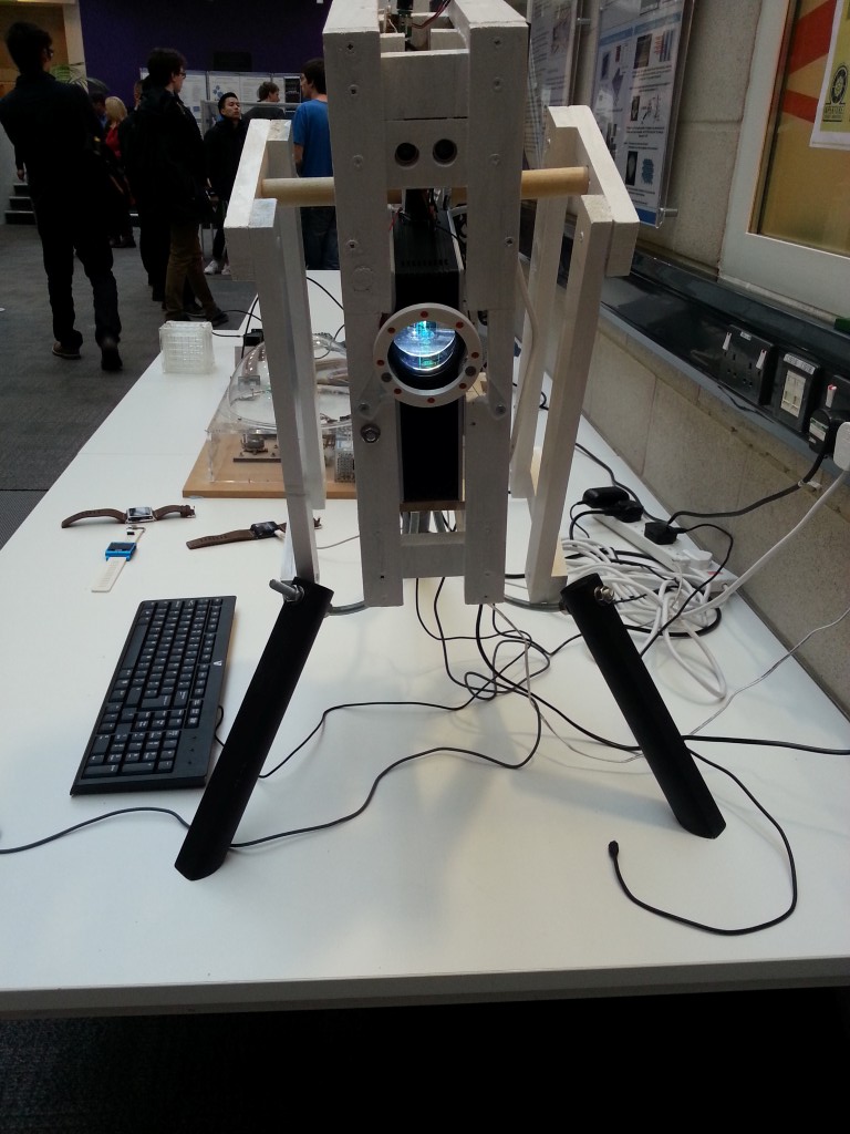
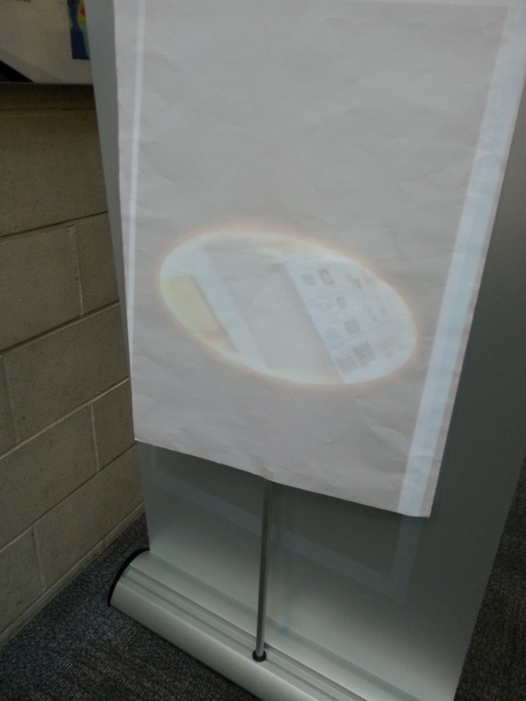
Coating the inside of the new reflector I’ve done some quick tests in a bright room and the output seems considerably brighter but the real test will be when it’s all bolted back in the turret frame.
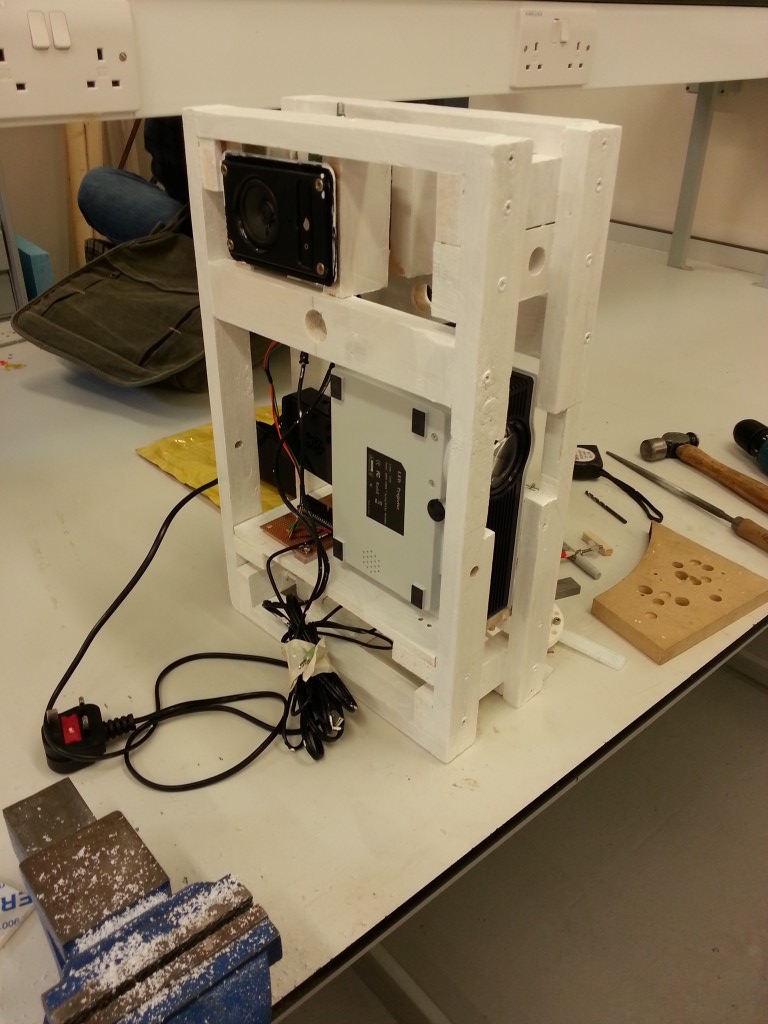
Next task shall be relocating the HDMI connector and fixing the LED array and heatsink permanently to the projector housing.
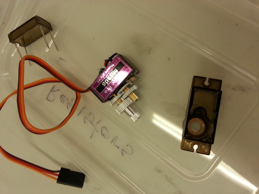
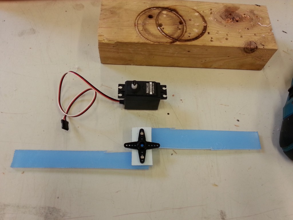
This time I have upgraded to metal geared servos however they are still locked to +/- 90 degees and so they need modifying for continuous rotation.
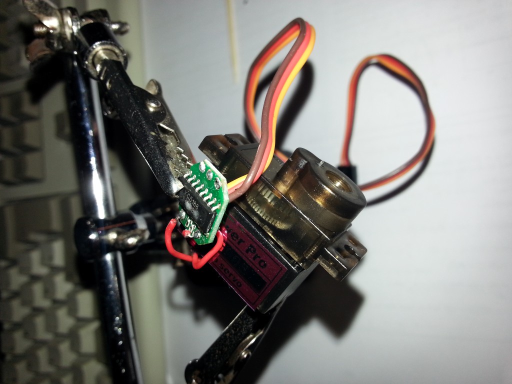
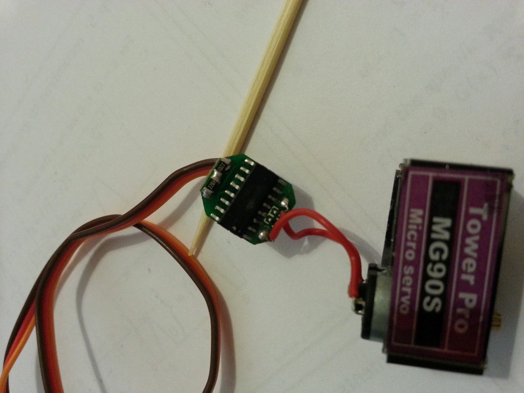
Here I am using 2.2k ohm 0.1% tolerance smt resistors to replace the potentiometer and trick the servo into thinking it’s locked in one postion.
Last time I used some random through hole resistors I had lying around and when it came to trimming the servos there was a lot of drift, far more than I could correct for, so this shall be a big improvement.
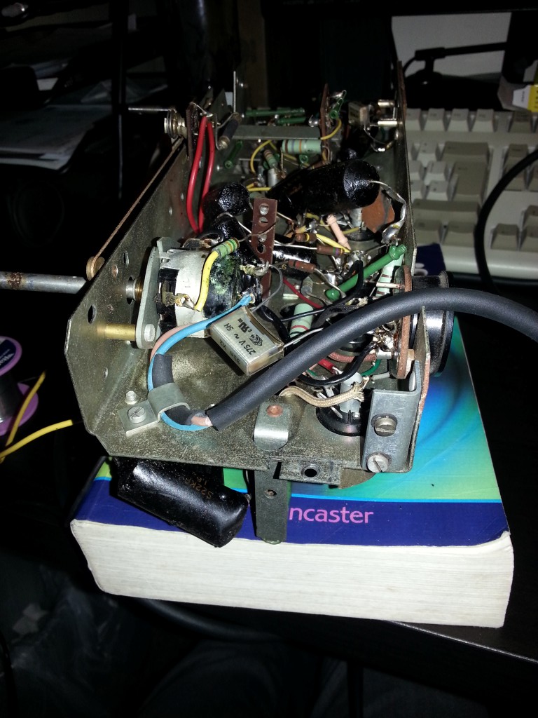
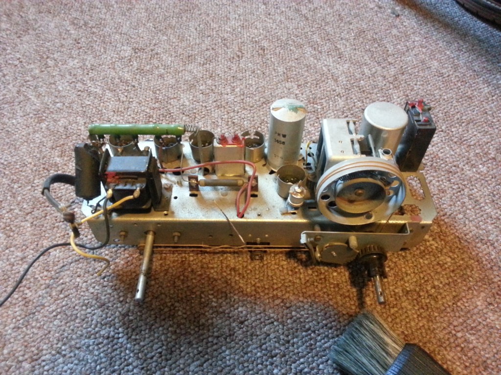
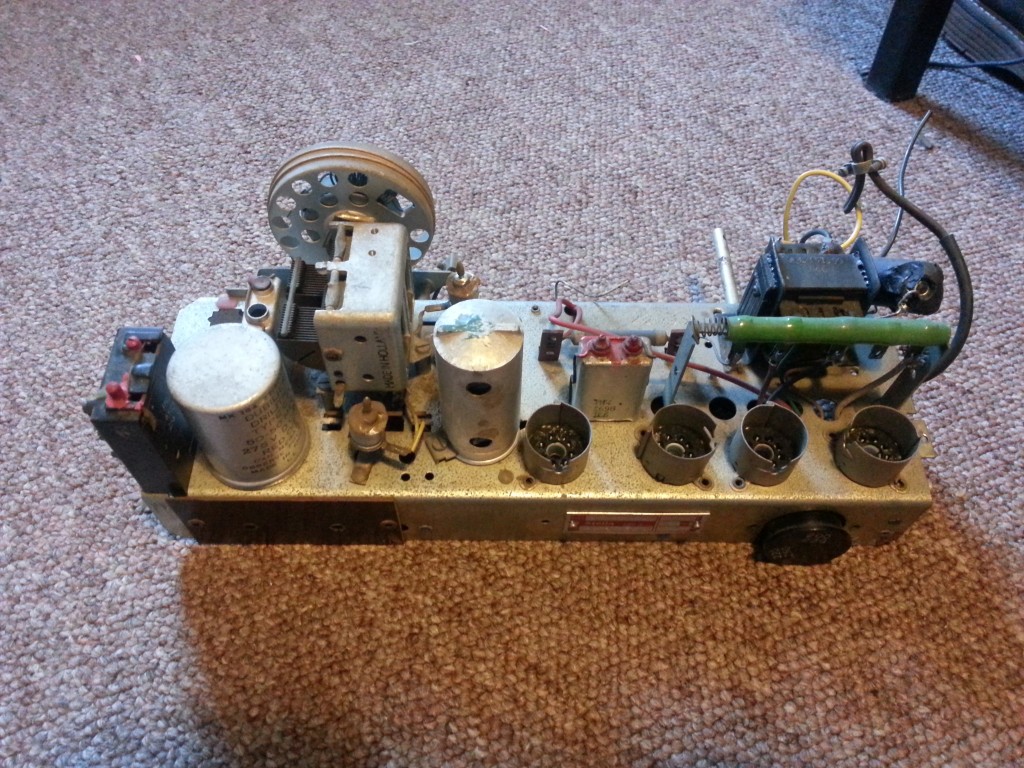
Before plugging in and testing this radio I replaced some choice components to improve the safety and reduce the chance of damage to other parts of the radio.
The original mains cable was the old twin core single insulation type and had become cracked and hard.
The capacitors replaced were the mains line-to-line cap, aerial-to-chassis earth and the audio output capacitor.
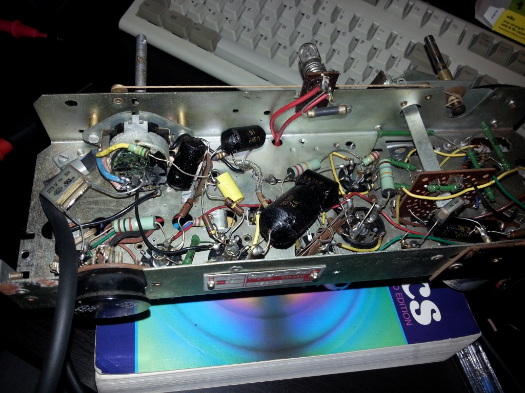
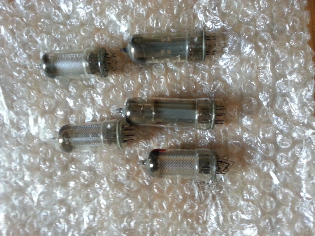
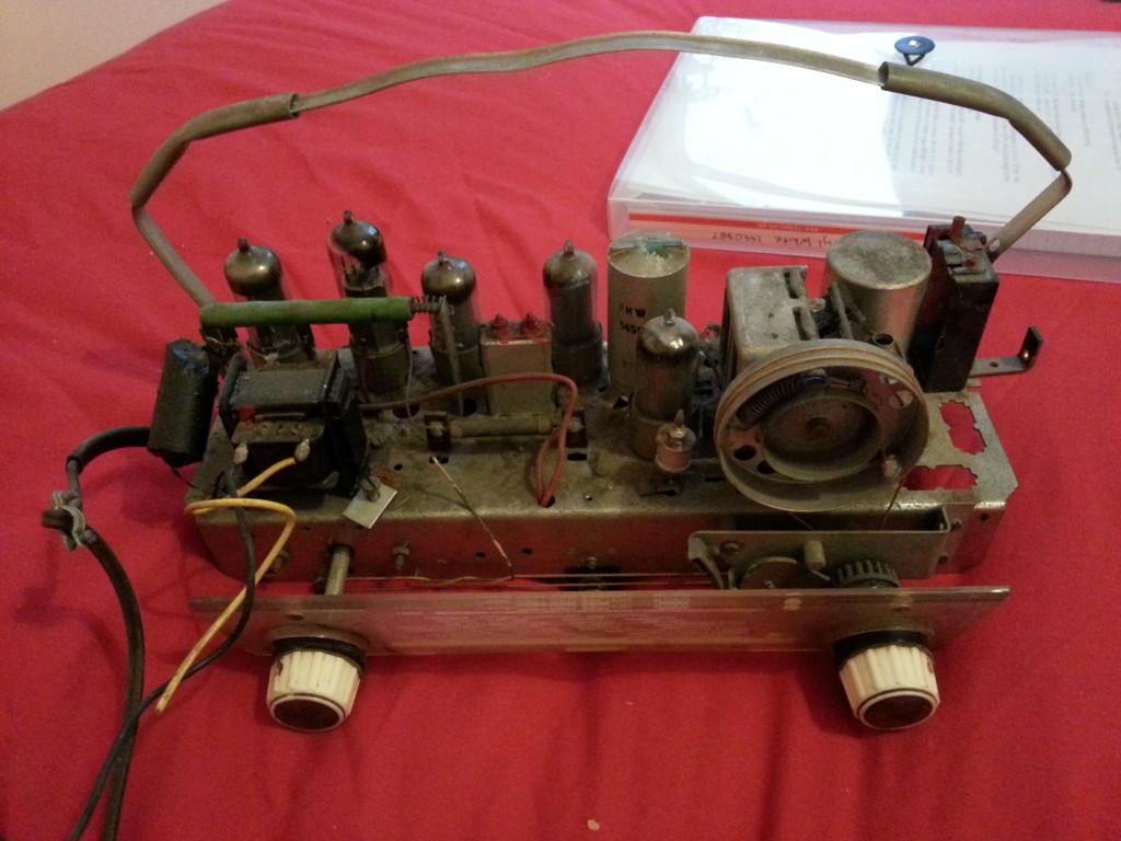
This is my first project in the world of valve based equipment and I’m very excited to be working on it.
I bought it as a non running chassis from eBay but it seemed to be relatively complete, missing only the outer body. This won’t be a problem as you will see since I intend to laser cut a perspex case for it.
Well that’s my 1st robot wars competition over and done with and I can say I have much to improve on !
Movement – Servos modified for 360 degree rotation have lots of drift and thus slowly rotate when you want it to happen least. Use proper servos or motors and drivers.
Battery life – 300 mAh batteries are fine but excess weapon motor useage will deplete them. Locate the charging port to somewhere that’s easy to access for charging between rounds.
Amour – All cables *must* be projected from cut damage or you risk losing the round early as the green machine experienced.
Overall though I felt I did alright and got through to the 3rd round.
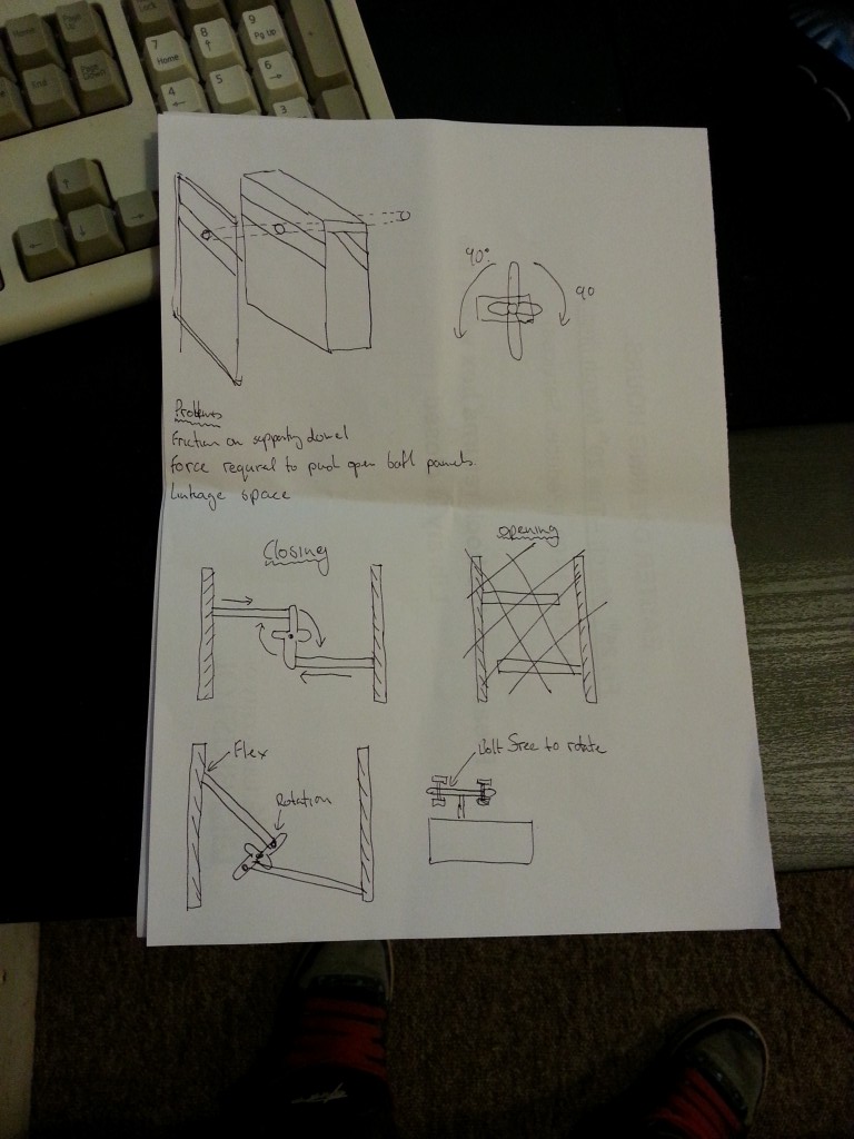
 I’m not sure how well this style of linkage will work but that’s what experimentation is for.