New components and completion

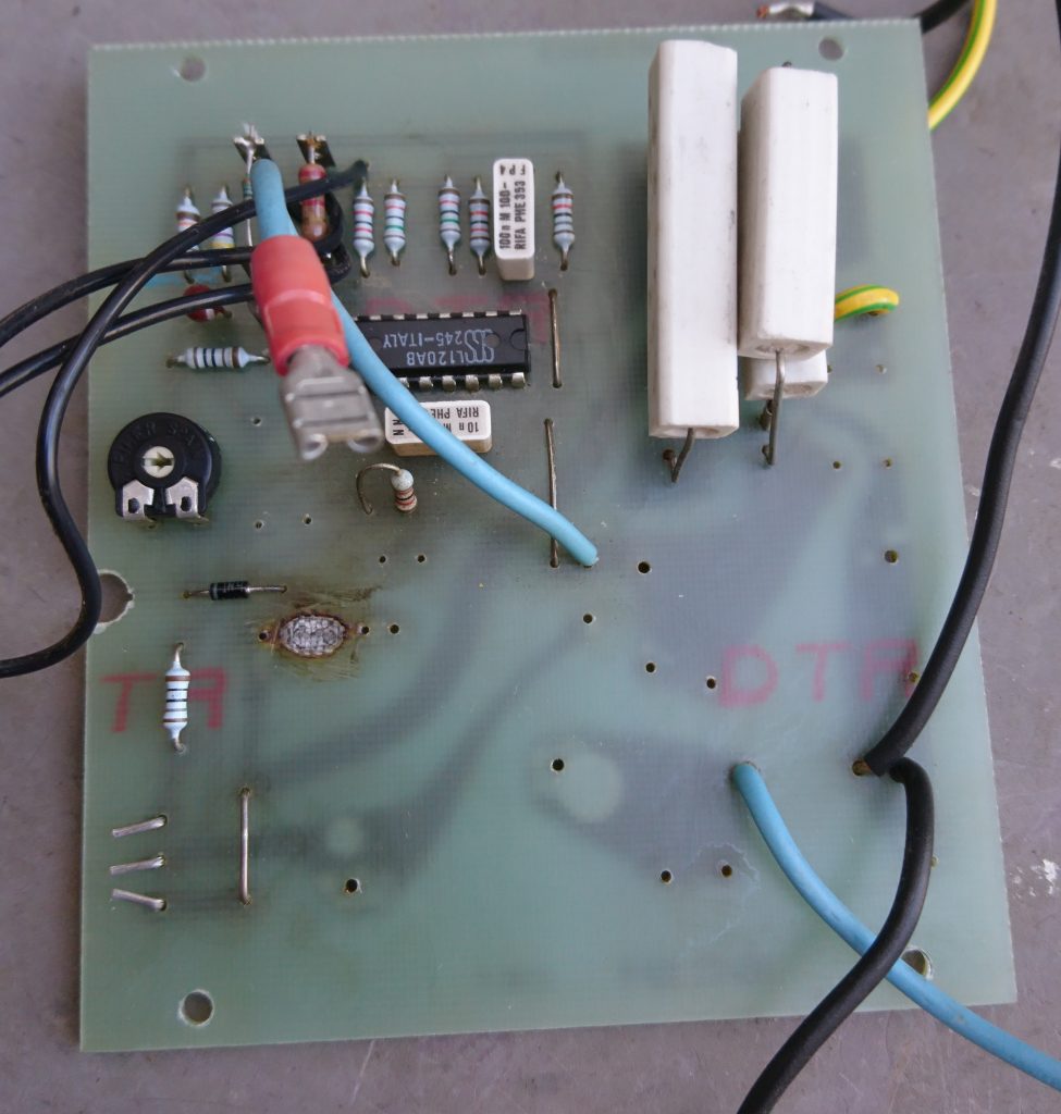
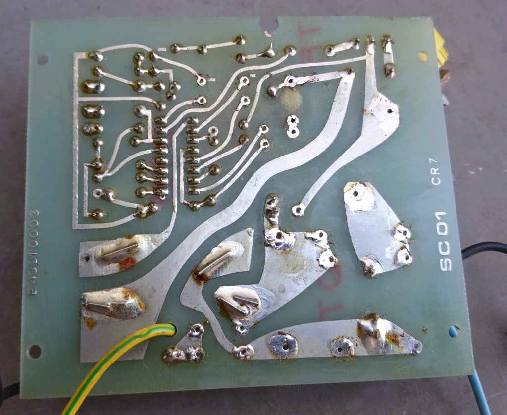
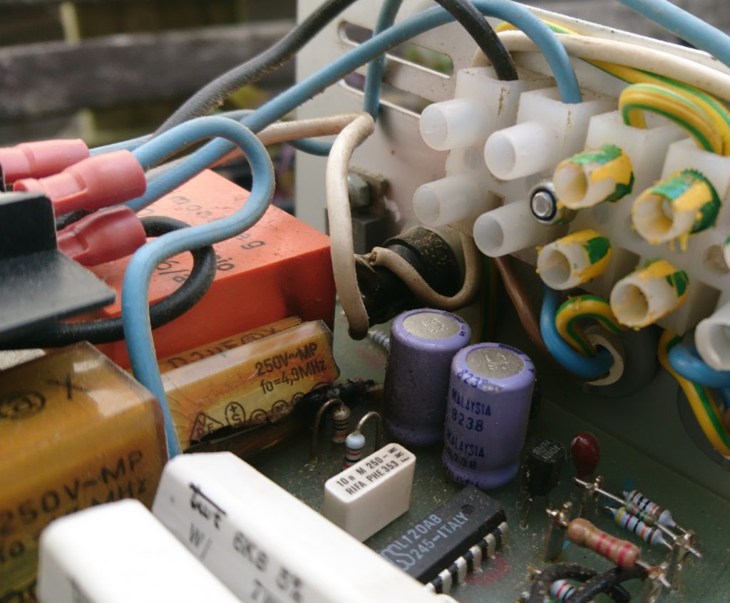
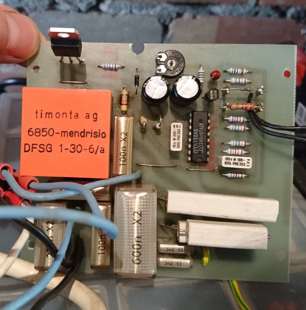
The following pictures show the new components and the completed board.

Capacitors

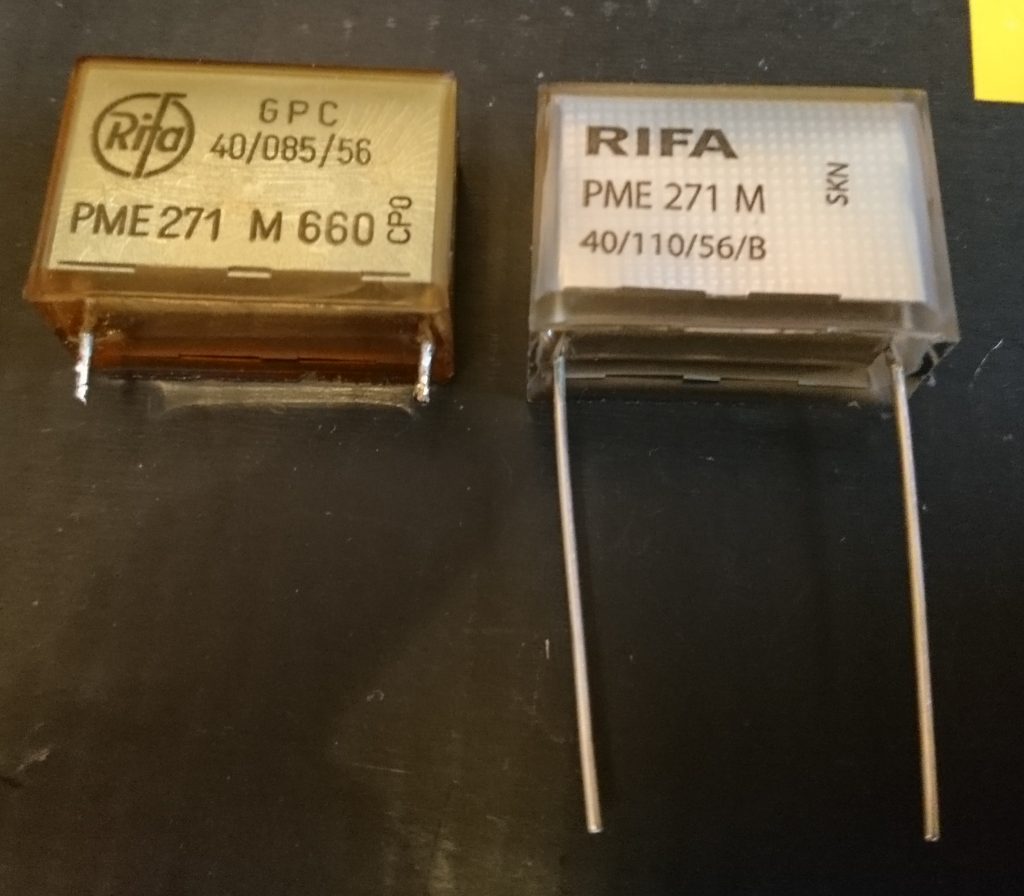
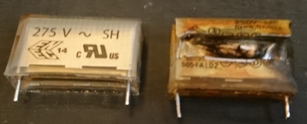
The above image shows the new and old Rifa capacitor. You can see the crazing and discolouring on the left hand side.

TRIAC

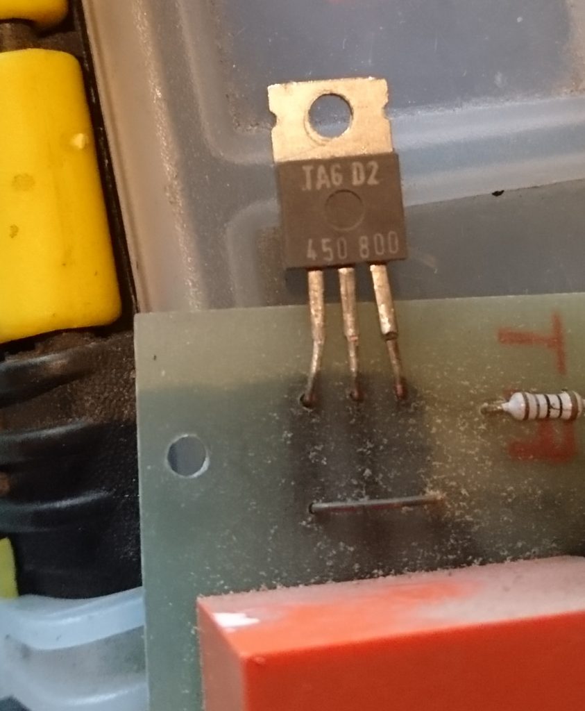
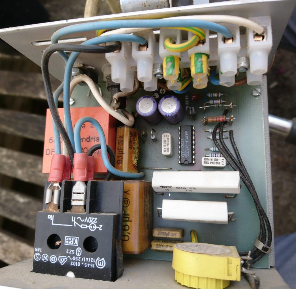
There was some difficulty in finding an alternative TRIAC. From the part numbers on the package, TAG D2 450 800 , I took a guess on the typical specifications as I could not find a vintage TAG Semiconductors parts catalogue. I used a ST BTA16-800CW with a blocking voltage of 800V and an RMS current of 16A.

Finished PCB

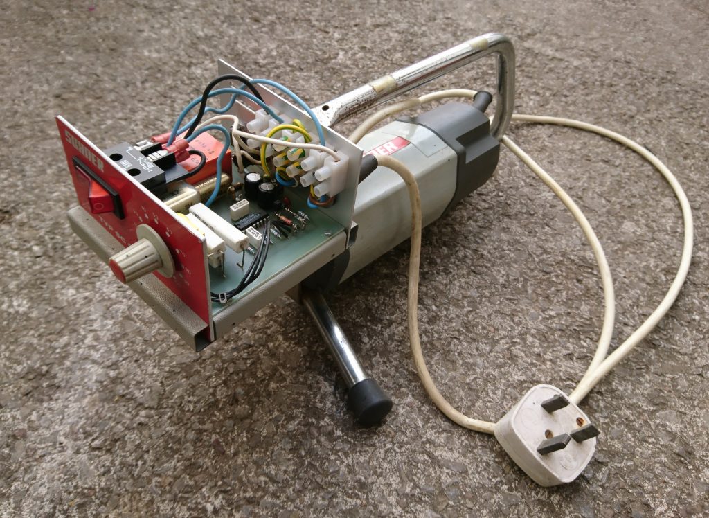
The motor is now working well unloaded and is surprisingly loud at max speed (28,000 rpm).

Watch this space for a reverse engineered circuit diagram.

PCB Cleaning

The following components were removed after inspection and shall be replaced:

2x 22pF Class Y
3x 0.1uF Class X
2x Resistors
2x 220uF Electrolytics
1x TRIAC – This was not faulty but the legs snapped on removal of the clamping bolt.
1x Inductor – Just for inspection.

Bare PCB

The failed resistor had become quite hot and burnt the top of the PCB. I cleaned this with a fiber glass pencil and applied a couple of coats of clear nail varnish afterwards.

Back of PCB

The back of the PCB shows some signs of the burning but it is still intact.

Damaged Capacitor

Above is the damaged capacitor next to it’s new replacement.

Strip Down

It soon became obvious once the lid was off where the magic smoke had come from and where the problem may lie.

Motor controller

The controller is full of the dreaded ‘Rifa’ capacitors, these are paper capacitors with resin dipped casing that breaks down with heat and age allowing moisture in. Once this happens a bang soon follows.

You can see the 0.1uF capacitor in the centre of the image has split open horizontally and in the background a resistor has also burnt.