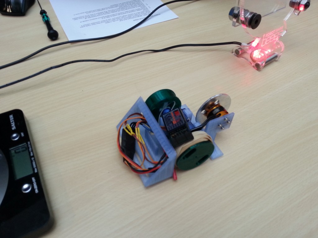
 This is robot being weighed and measured before the start of the competition
Author Archives ⇒ daryl
Chassis iterations
The next few updates shall be a brief collection of pictures I’ve taken during recent projects.
3 stages of chassis prototyping
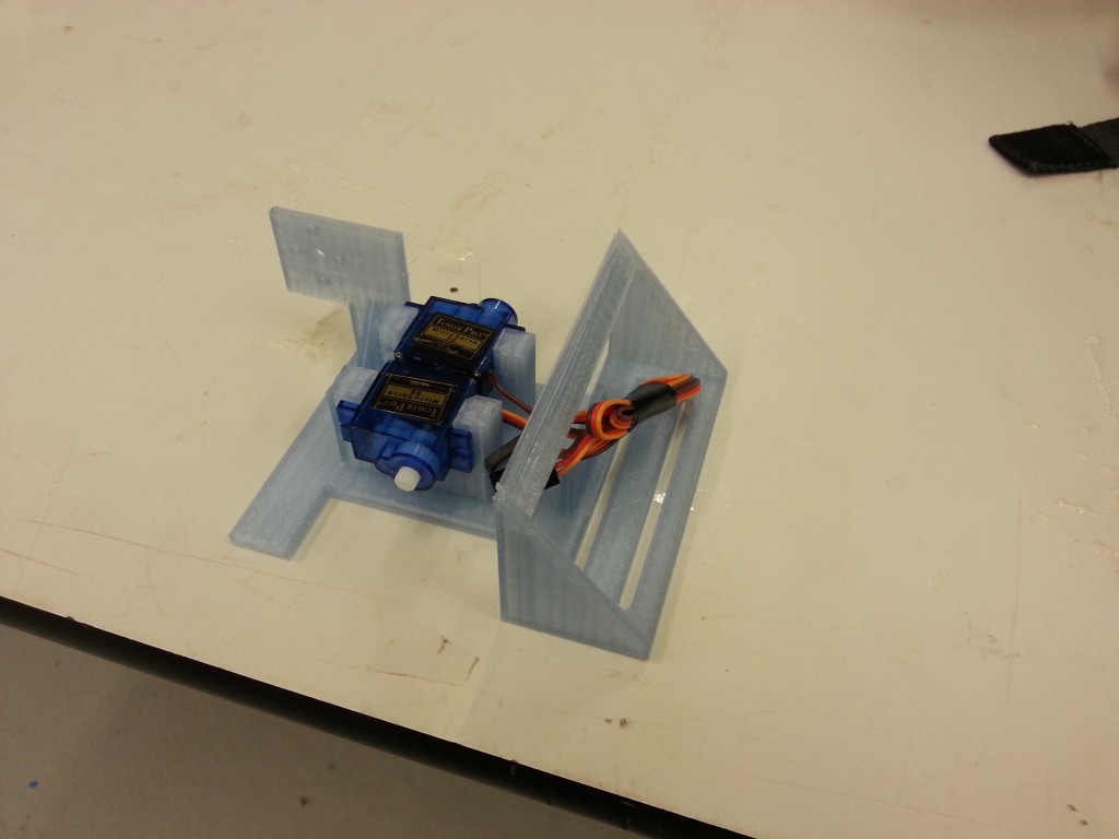
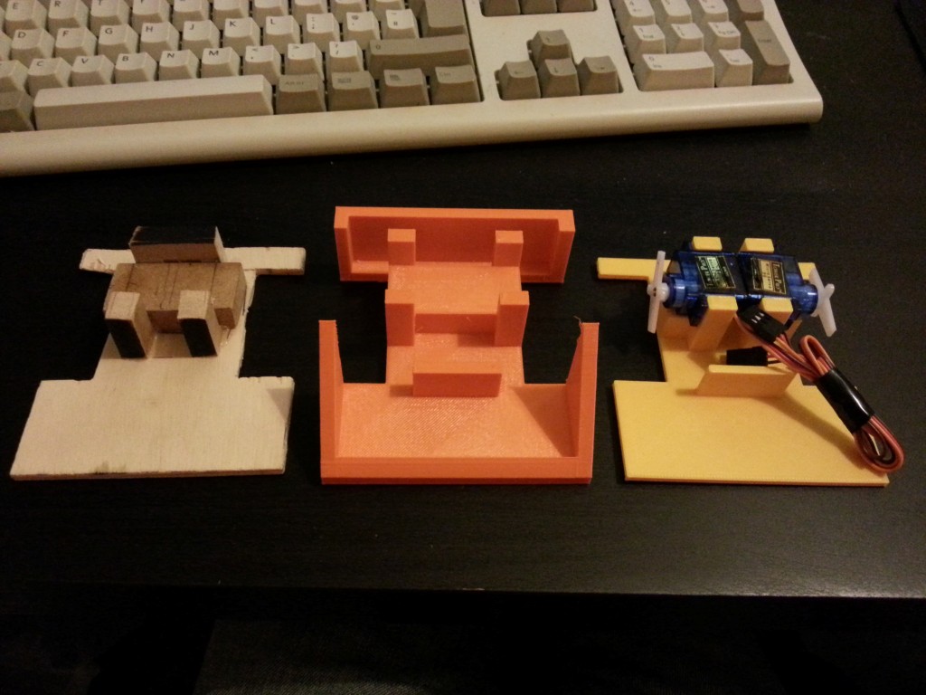 Final chassis
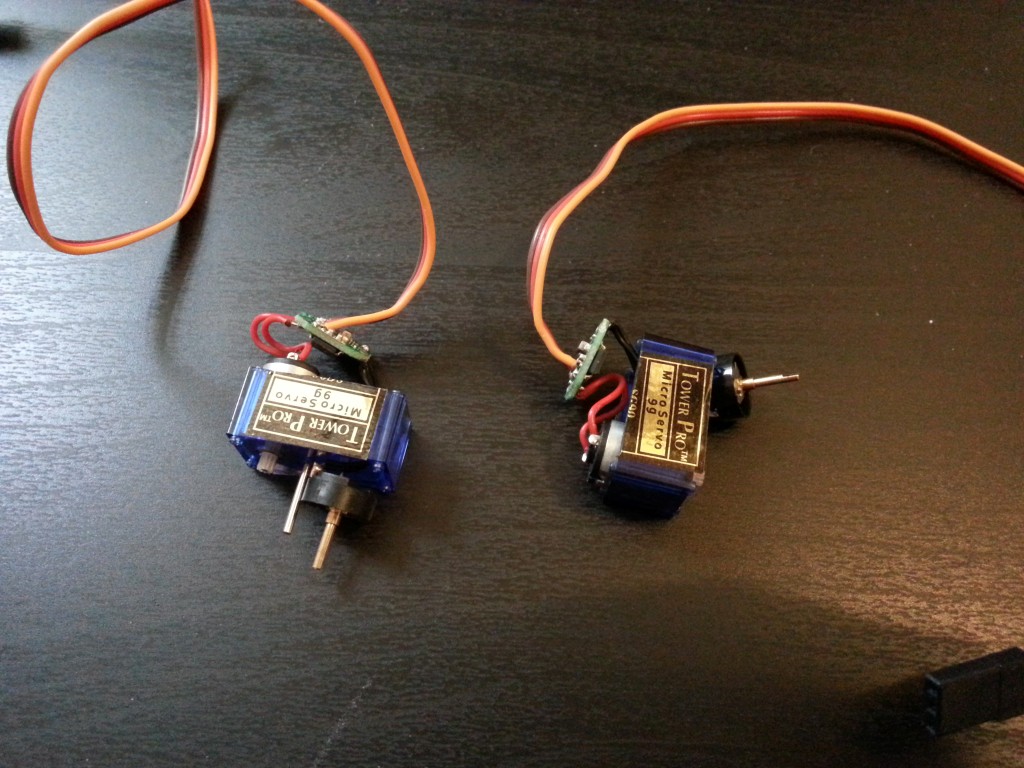
Servo modification
This post is a few pictures showing the modification of SG90 servos so that they rotate 360 degrees rarther than the standard 180 left/right.
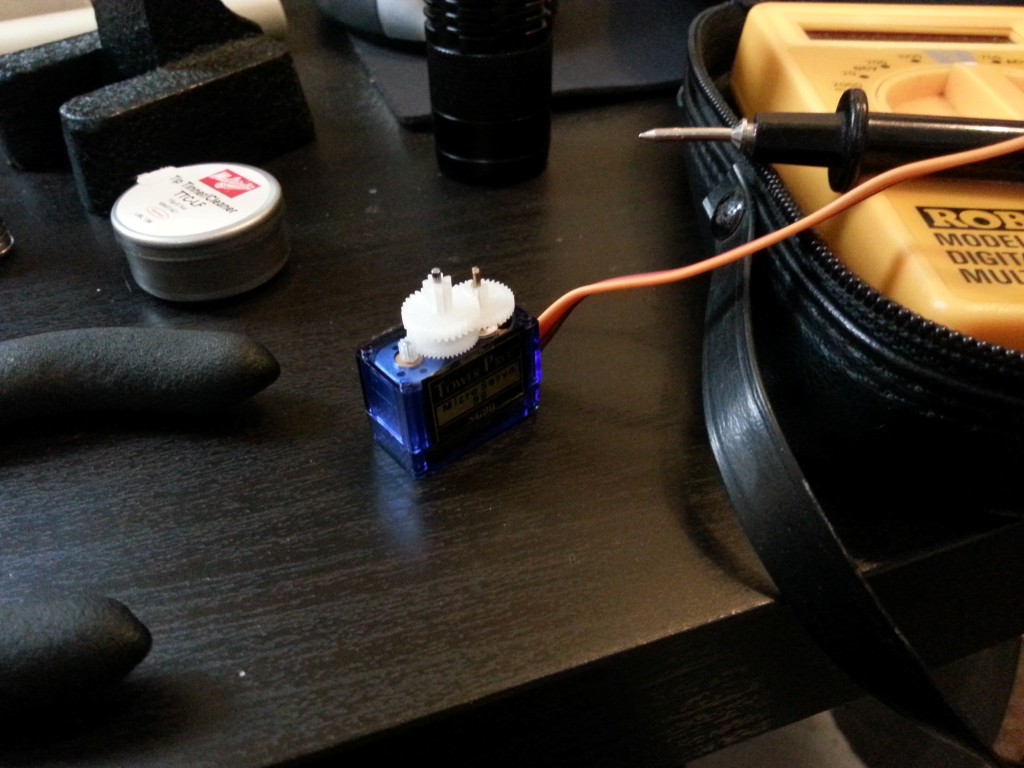
Bottom casing removed and you can see the control board, motor and potentiometer.
Here is the servo with the top half of casing removed. One of the gears has a pin that physically stops full 360 degree rotation so that must be cut off.
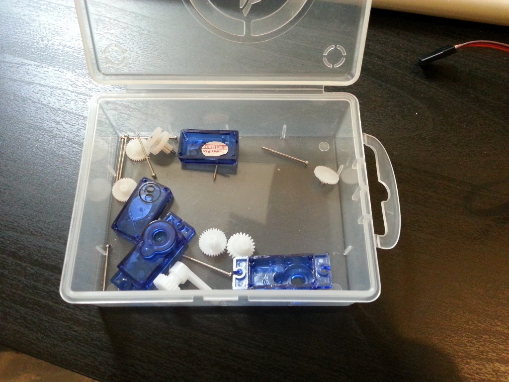
Small pile of gears and drive shafts.
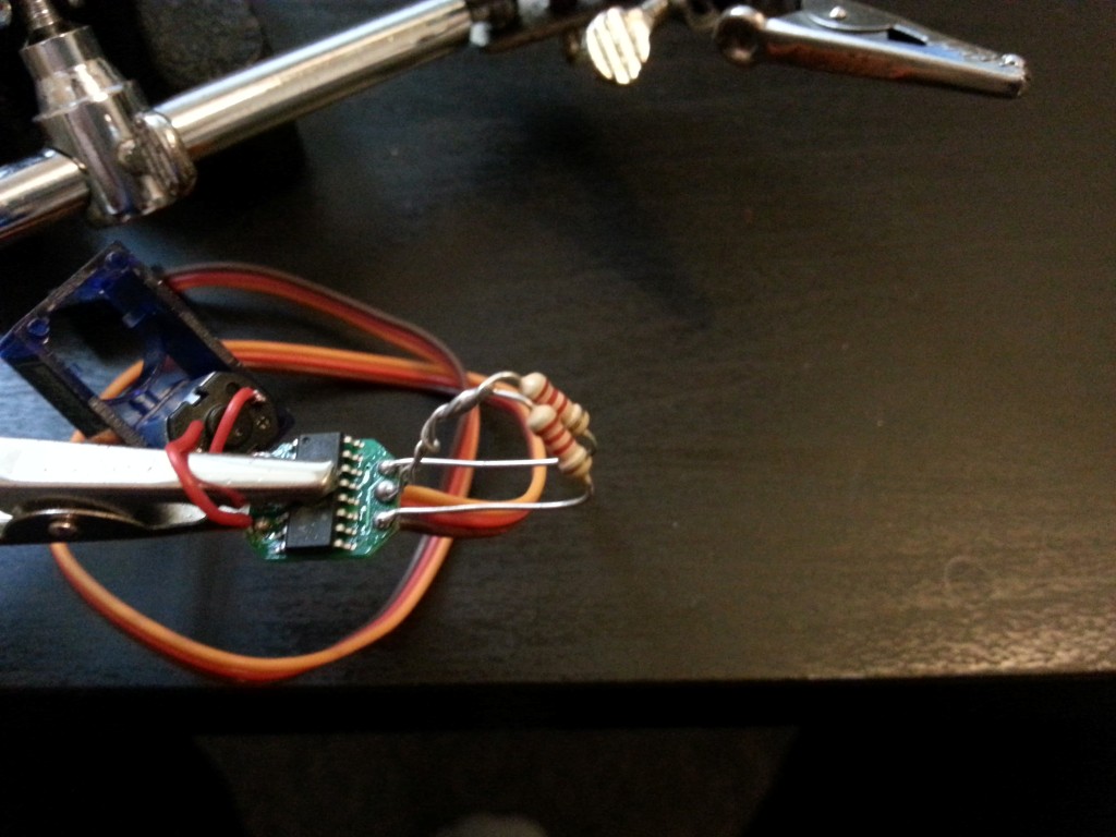
My first attempt at soldering a pair of resistors in place where the potentiometer previous connected to. This is to trick the control board into believing it has not rotated far enough yet.
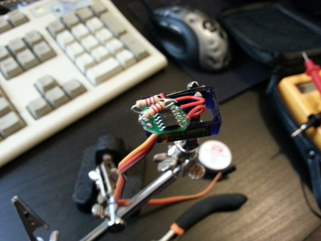
2nd attempt on the other servo, space is very limited when you put the end casings back on so you really need to shorten the resistor legs as much as possible.
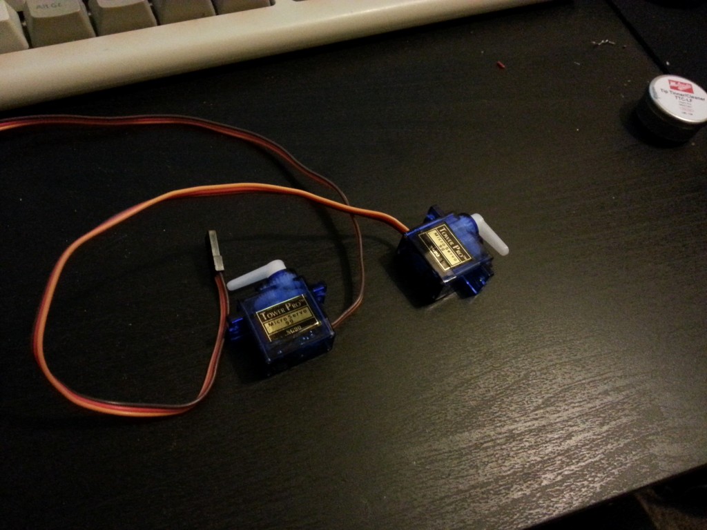
And back together ready to act as drive motors for my robot.
Robot Wars Inspiration
When I used to watch the 1st series of robot wars I always planned to emulate ‘Roadblock’ as its simple shape and mechanics seemed easiset for me to recreate at home. Since I was in school then, that never really took off but now I have the money and equipment to make an ant-weight hommage to ‘Roadblock’ for the BEEES robot wars.
Here is a link to the wiki where you can find out about ‘Roadblock’s various wins.
Robot Wars
Well it’s the start of the new term and so that means BEEES will be hosting it’s robot wars competition. Inspired by last years tournament I’ve decided to enter myself and on this page you can see my progress.
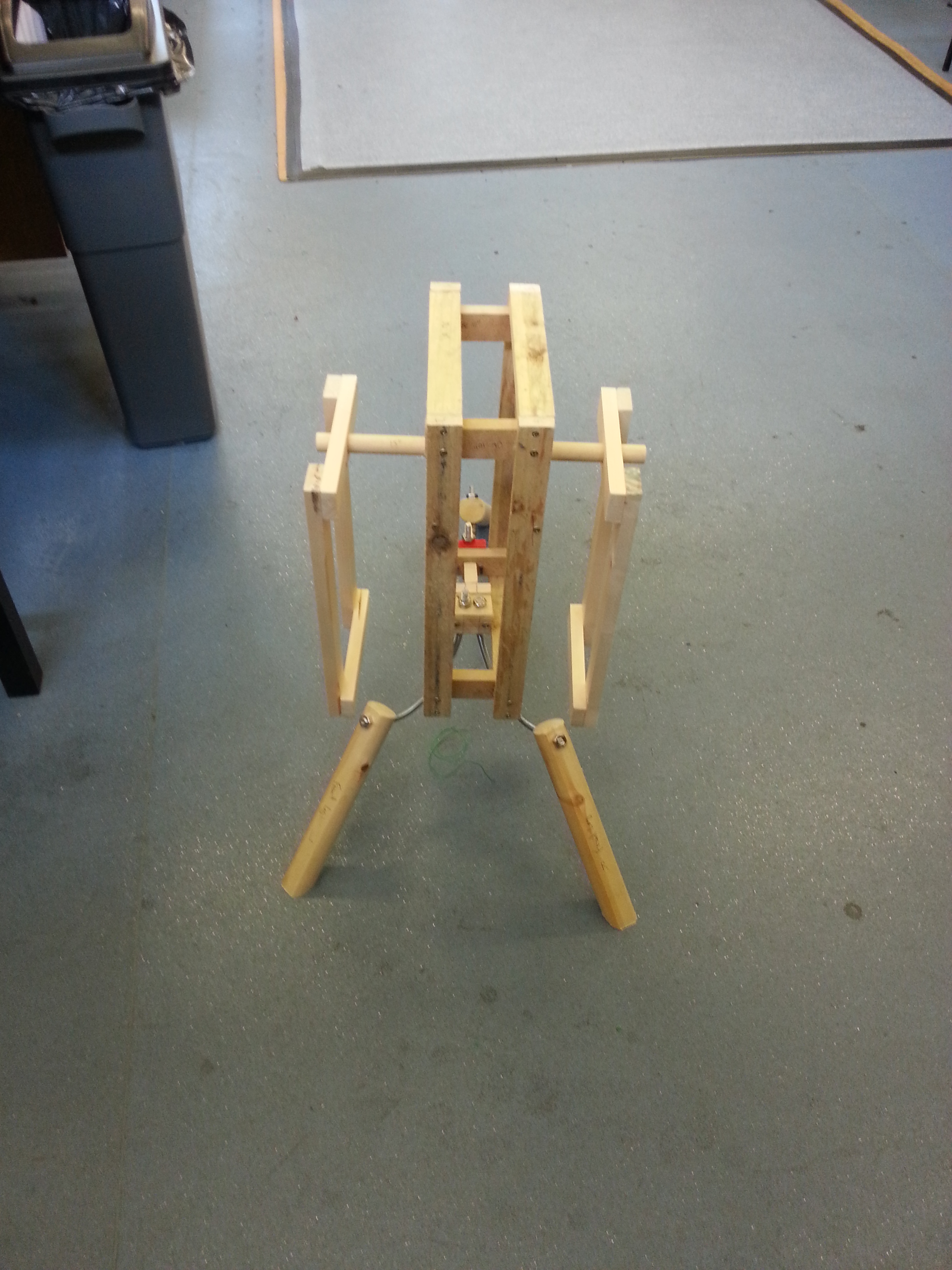
The day of reckoning…
It stands!
Well after adjusting the legs and making good use of a spirit level I’ve managed to increase the stability of the turret to beyond that of a 3 legged goat.
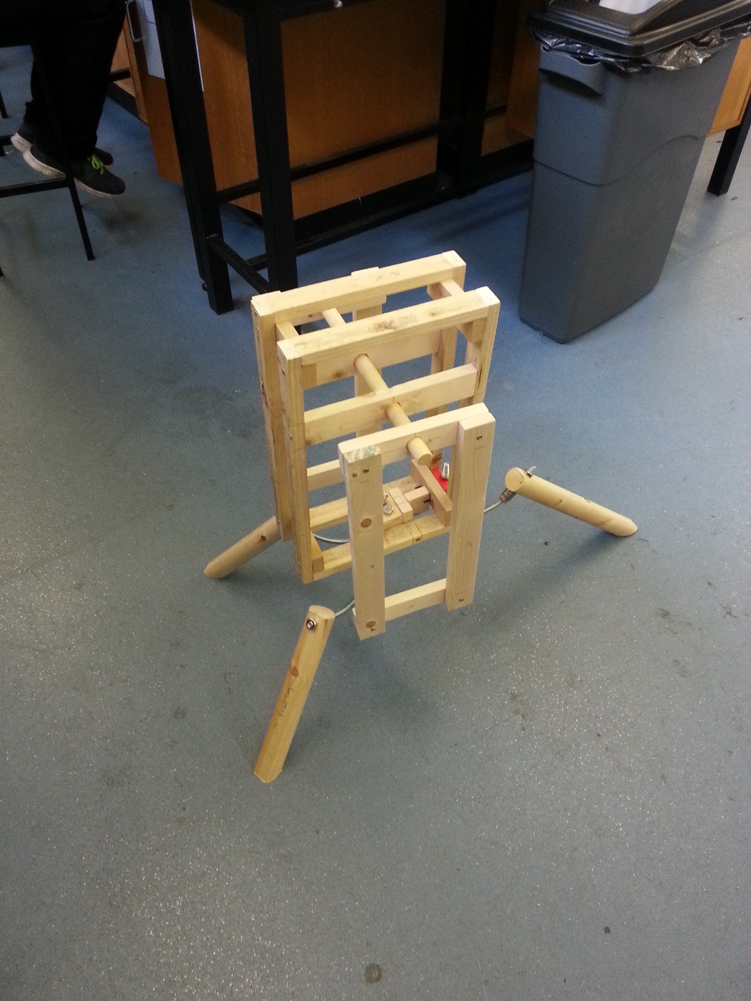
Next task was to cut the bottom of each leg at an angle so the entire surface of the leg would make contact with the floor whever it was placed. This was very much trial and error but I did use a fancy protractor.
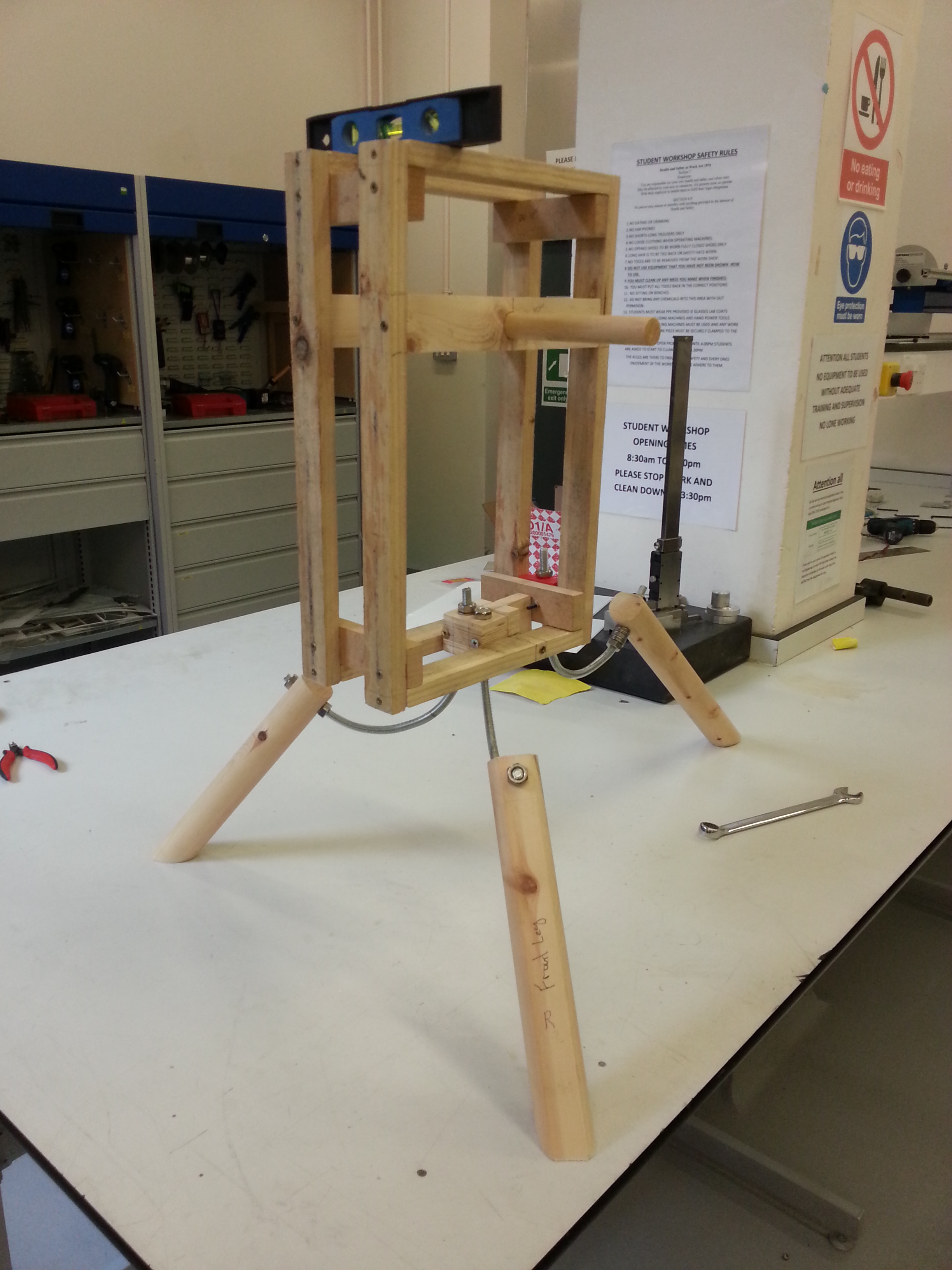
I have some foam sticky pads to add to the legs just to increase grip that little bit more.
Here is a shot with the fixed side panels fitted.
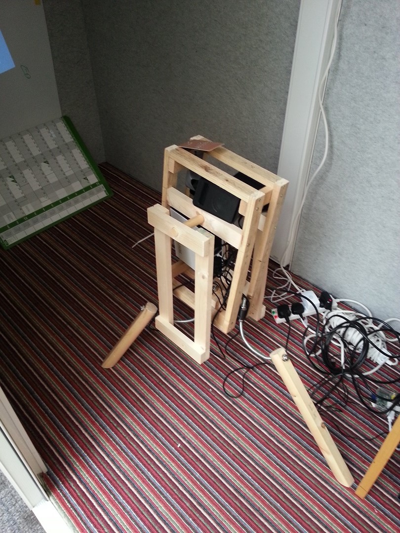
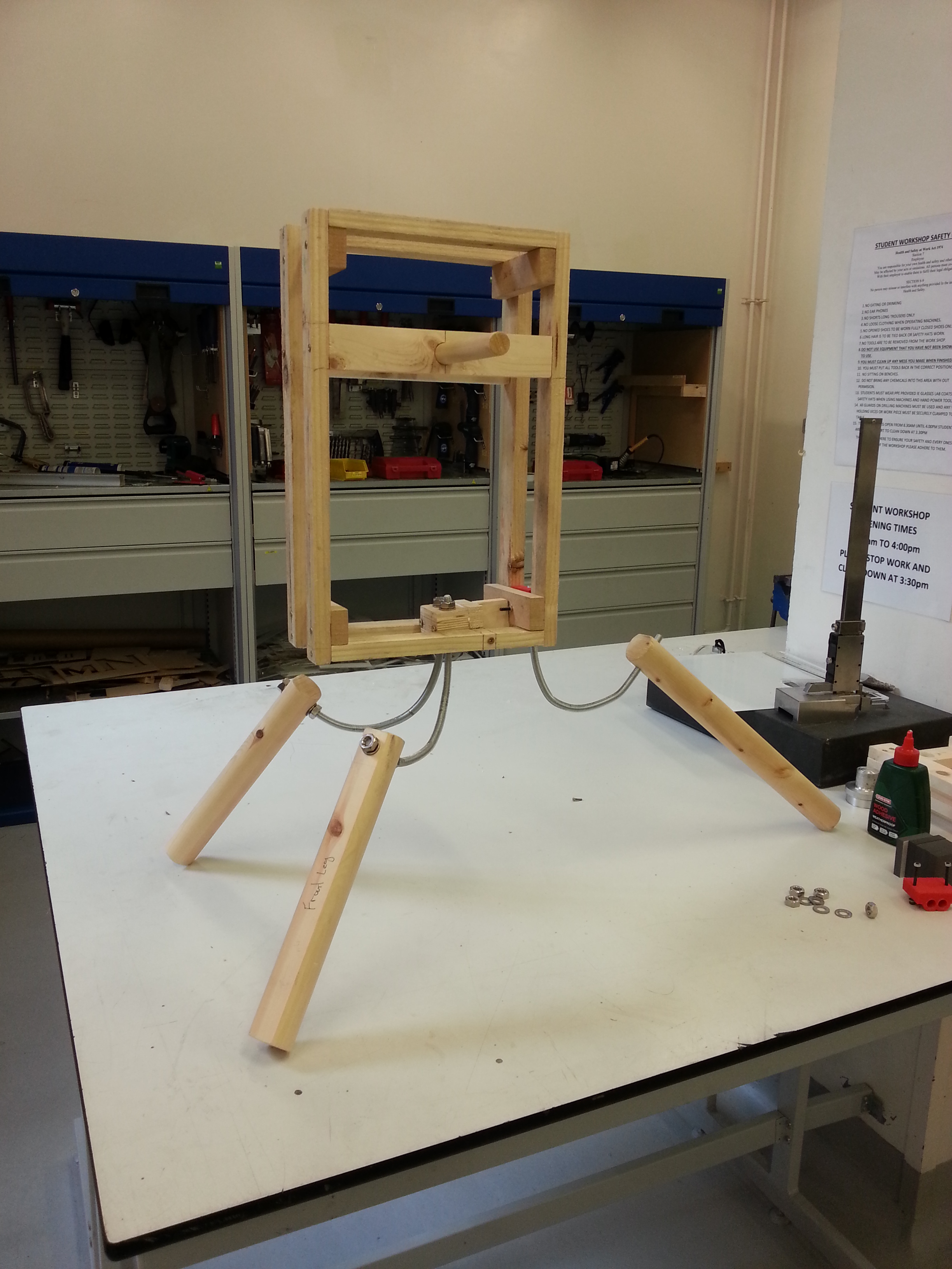
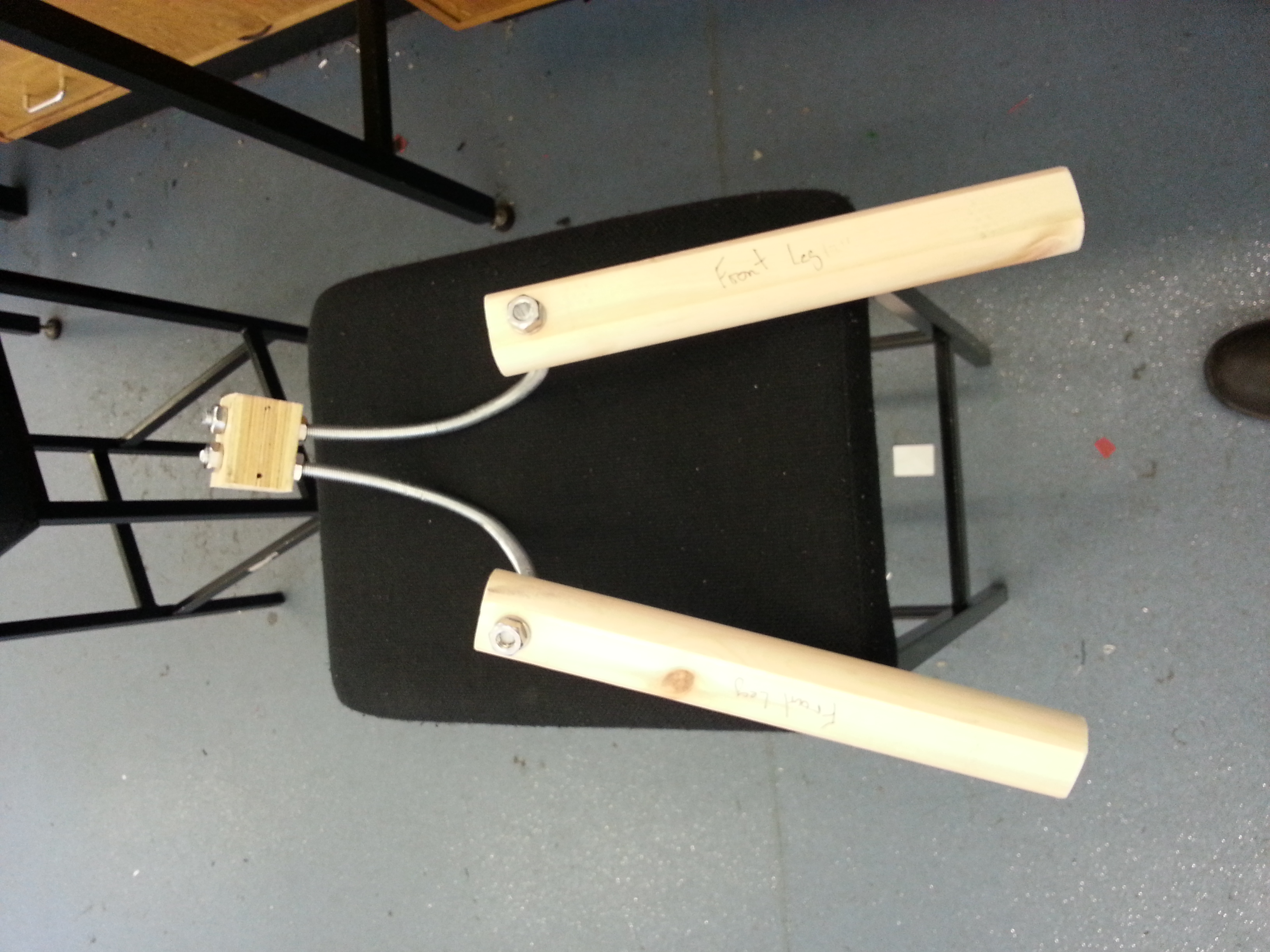
The turret body gets legs
Being a little short on time I remade the front leg bracket with a block of wood. It’s rough but functional and still allows room to adjust the leg height.
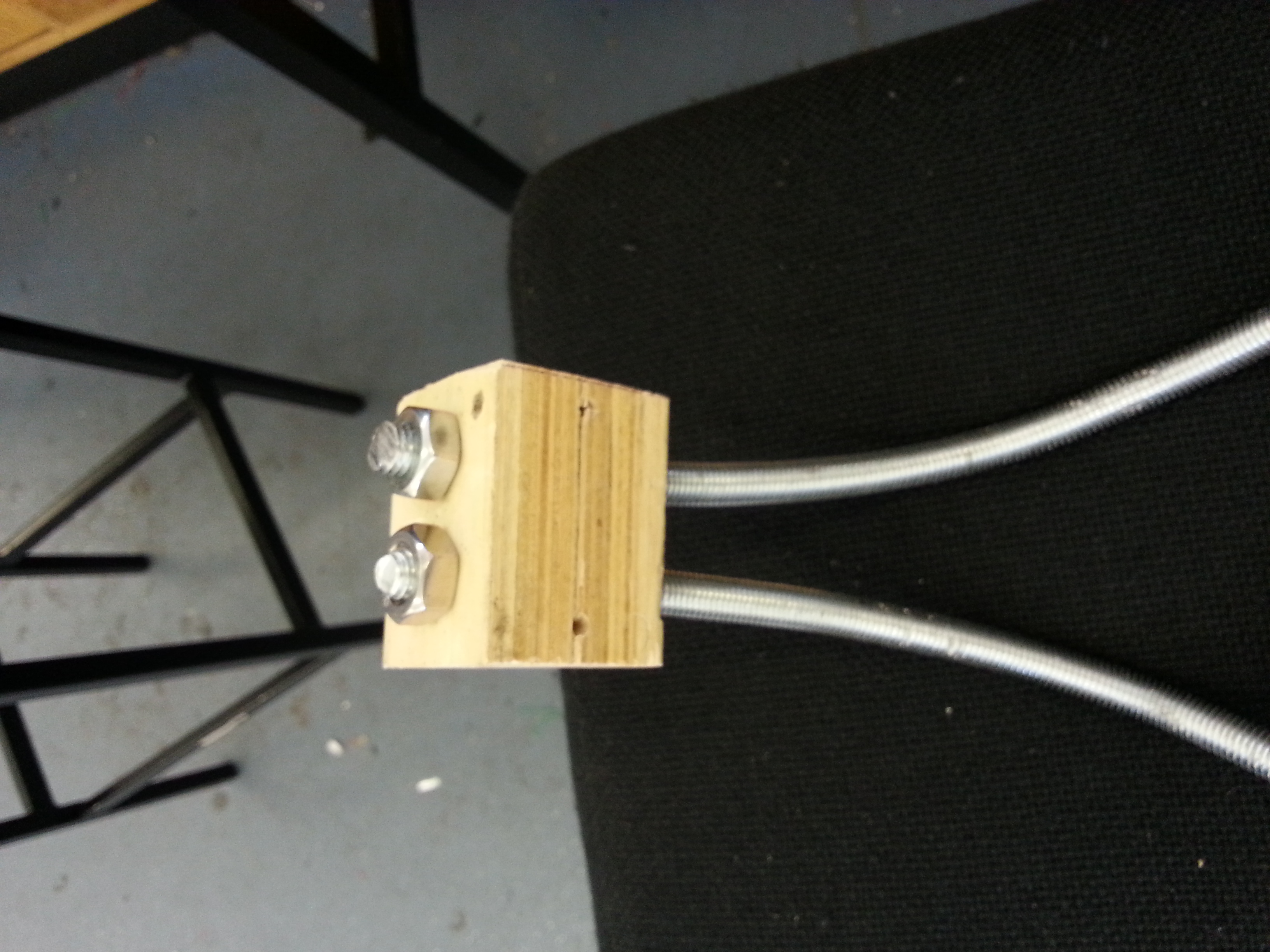
Legs loosely bolted in position.
3D Printed Camera Holder
Well as the title says this is a camera holder for the official ? raspberry pi camera board. You don’t get much with the camera and I wanted a simple mount that offered rotation so this was ideal. You can find it on Thingiverse.com and it plugs into the ethernet port meaning it’s compatible with almost every style of case out there.
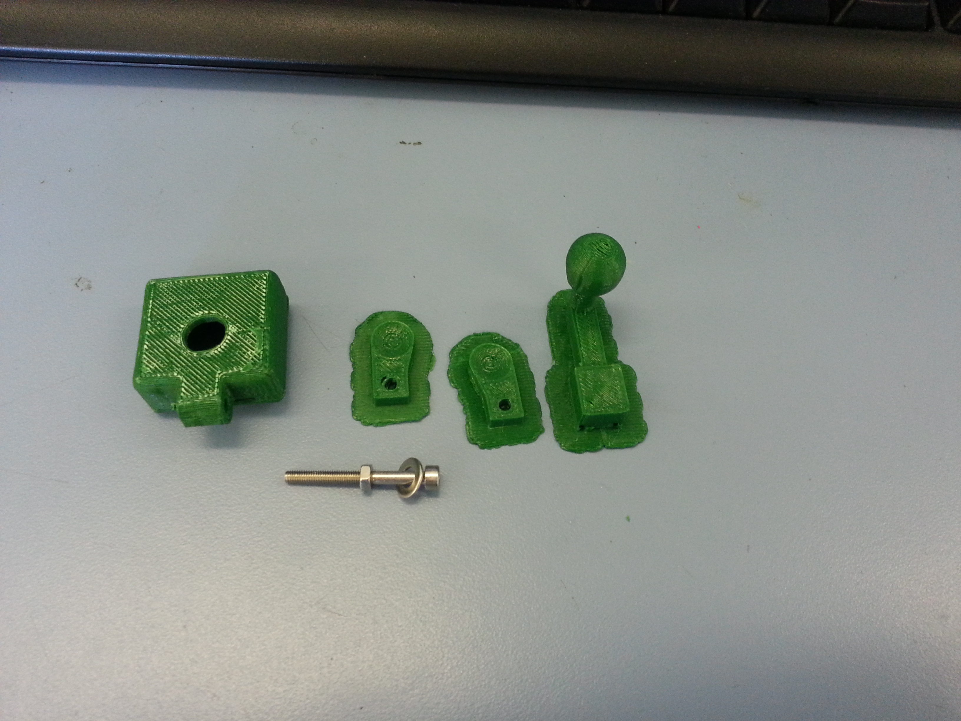
This is hot off the printer and you can see the “rafts” still attached.
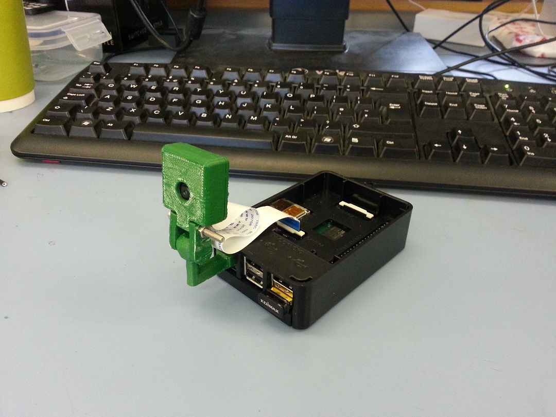 Excess plastic cut off and assembled.
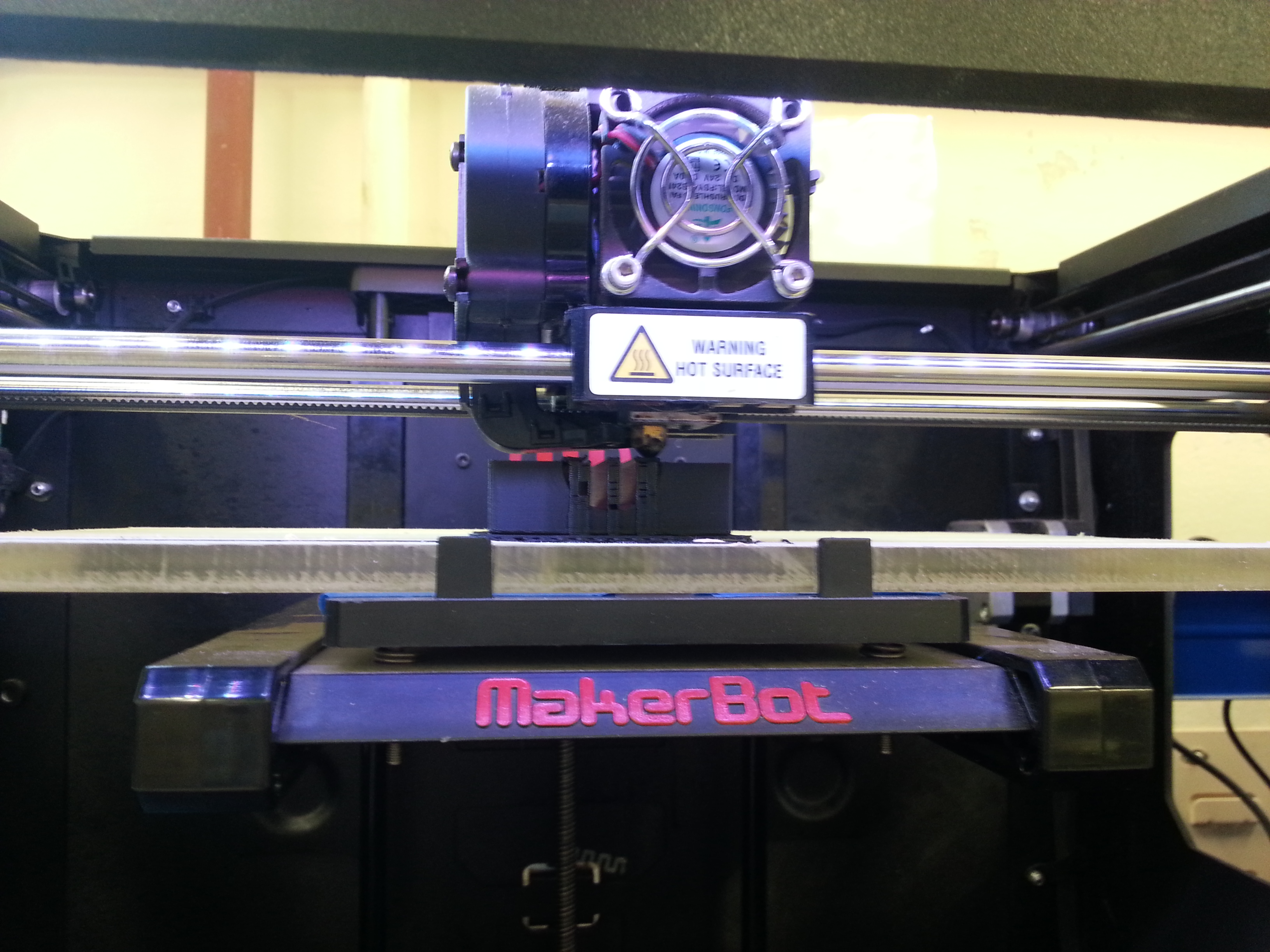
3D Printing…
Today’s post is really just a collection of images and videos showing off 3d printing for those of you who haven’t seen it in person. It’s good fun when it works.
This is the printer just starting off and it’s laying a thin base of material to help the full part stick to the platform.
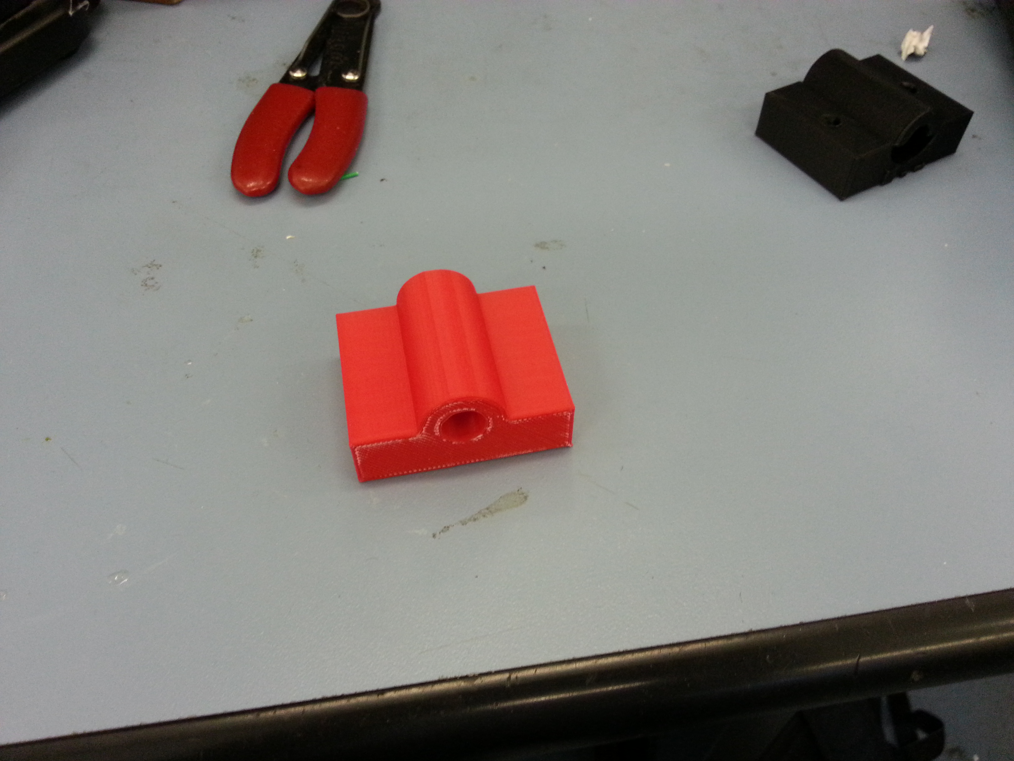
Here is a successful bracket that will hold the back leg in place.
This video shows the printer part way through the prototype bracket.
And this one is the base of a miniture portal turret model.