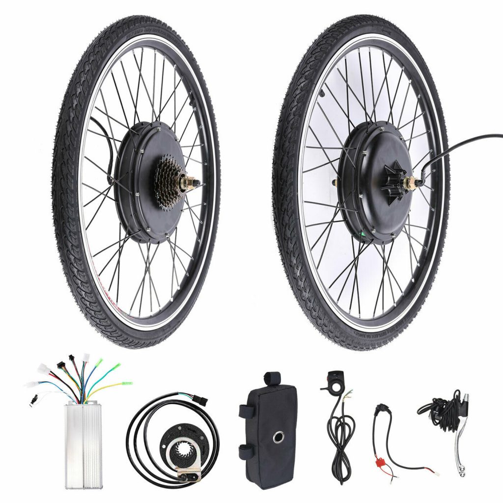
I purchased a 36V kit from eBay which includes a 26″ rear wheel with hub motor, motor controller, switched brake levers, throttle and pedal assist sensors.
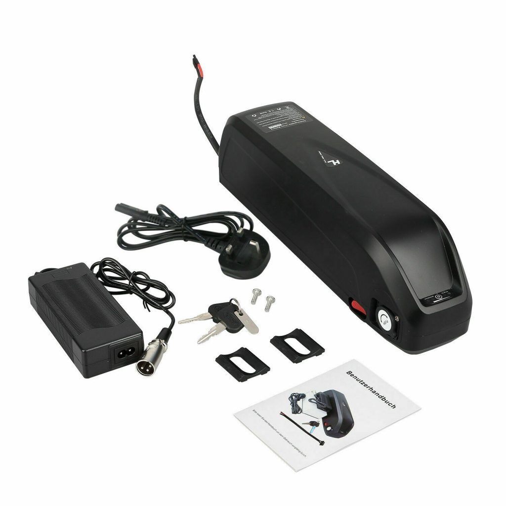
The battery is a 36V 15Ah unit with a downtube/bottle cage mount.
I purchased a 36V kit from eBay which includes a 26″ rear wheel with hub motor, motor controller, switched brake levers, throttle and pedal assist sensors.
The battery is a 36V 15Ah unit with a downtube/bottle cage mount.
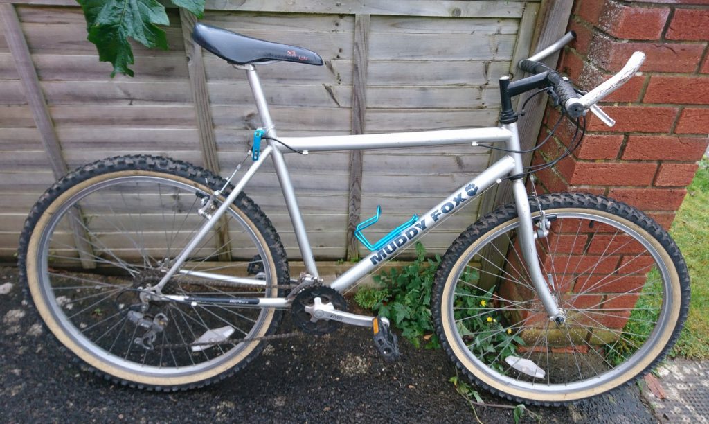
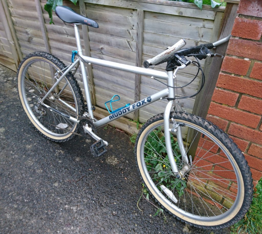
I found a 1990’s ‘Muddy Fox’ mountain bike to use for the basis of this electric bike conversion. Old steel frames have some advantages over modern aluminium frames when it comes to wedging large motors in them.
The original coilgun circuit used a relay which quickly suffered from contact problems due to the large current flow so I have replaced it with a thyristor.
I’m using a FS2514MH thyristor with an non-repetitive on-state current rating of 330A.
Datasheet: https://www.fagorelectronica.com/images/download/semiconductor/fs25st.pdf
I took the oportunity during testing to record the current waveform using a LEM PR1235 current probe.
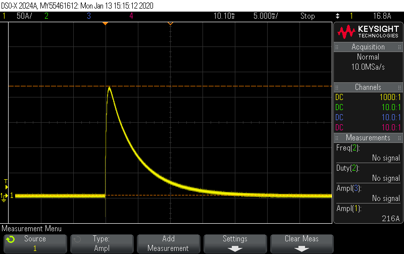
As you can see, the peak current is 216A.
The updates have been sparse but here is a brief list of what I’m working on.
I hope to write a longer post soon with more details on the low cost power meter.
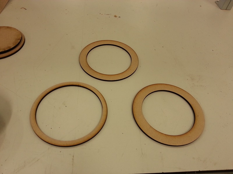
I laser cut a series of wood circles to clamp the original speaker then made some brackets out of spare perspex type material I found in the workshop.
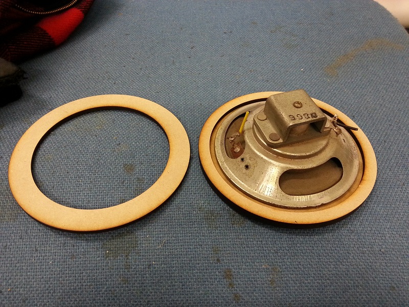
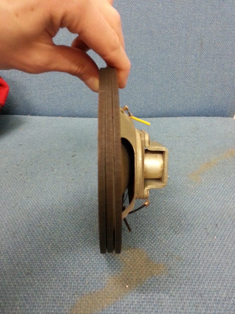 The speaker is held in place by the clamping pressure from a few nuts and bolts.
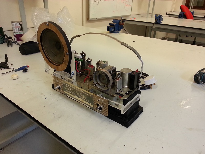 Here you can also see the radio band dial also mounted in the same manner.
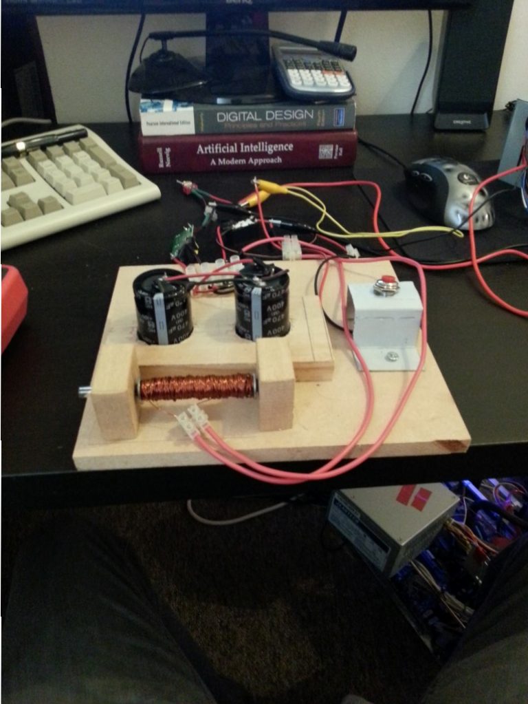
Test bed is now wired up and with connector blocks so I can swap out parts.
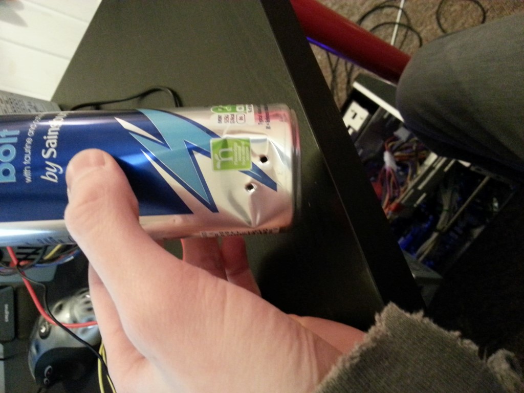
Here is a quick demo shot against a energy drink can.
And the damage done.
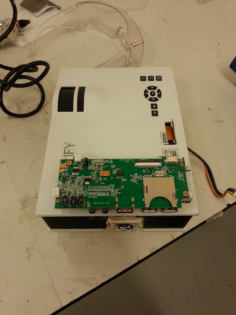
With the new reflector fitted everything was looking great however I soon discovered that all the ports such as HDMI, Audio Out and USB were blocked by the large heatsink keeping the new LED array cool.
I had 3 options :
Unsolder the HDMI connector and extend it.
Move the PCB to outside of the projector housing.Find a smaller heatsink.
I choose to simply move the PCB and so 2 slots were cut into the top housing to allow the flat flex LCD cable and control panel cable through. Along with this I also added perspex standoffs to mount the PCB and give clearance to the components on the bottom.
And in the image below it can be seen mounted in the turret frame with some protective packaging on the flat flex cable.
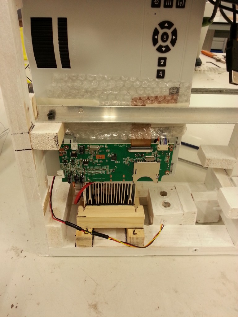
At some point I shall strip the projector down and clean it out with compressed air and polish all the lenses etc as a lot of debris has entered during the modifications
I made this simple wooden test bed to hold all the parts of the coilgun securely. When firing there is some recoil so it’s good to keep everything in place.
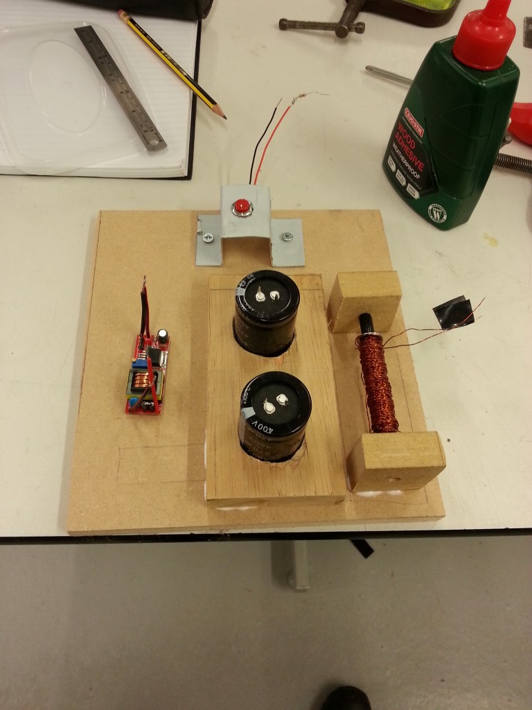
The small PCB on the bottom left is a mystery chinese DC-DC boost converter. The control chip had it’s part numbers ground off but I manged to read them under a bright light and it’s a flyback based design. Takes 5V in and gives a nice 300-400V which is perfect for capacitor charging.
I made this tool so I could discharge the large capacitors I’m using in a controlled maner as just shorting them with a screwdriver leads to big sparks and contact errosion.
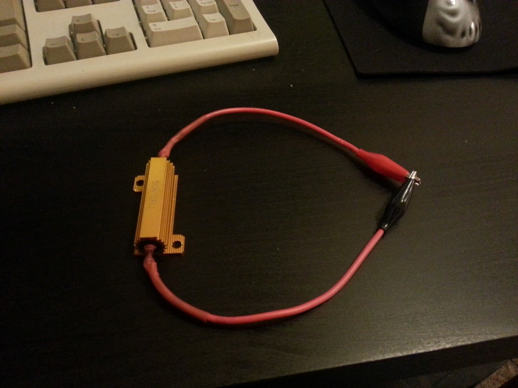
It’s simply a 10 Ohm 50 Watt power resistor attached to a nice thick cable and some crocodile clips all with plenty of heatshrink. I settled on 10 Ohms after doing a few rough calculations given the level of voltage I’d be using it at.