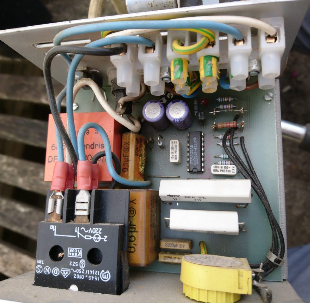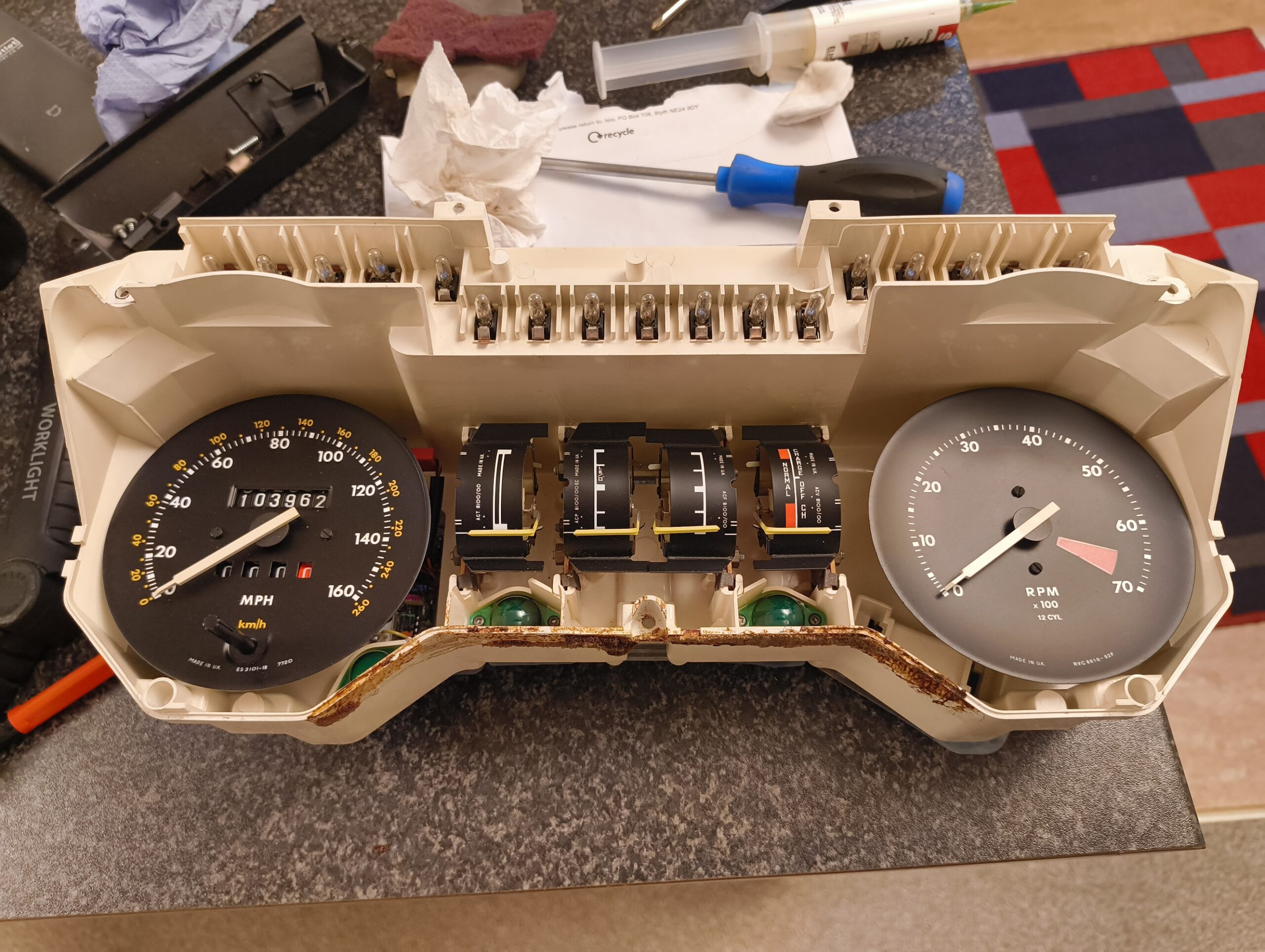
The odometer stopped working in my XJS so I took apart the instrument cluster to investigate futher. It’s an electromechanical system that starts with a VR sensor mounted to the rear differential before being signal proccessed into something that can turn a motor and the odometer gears.
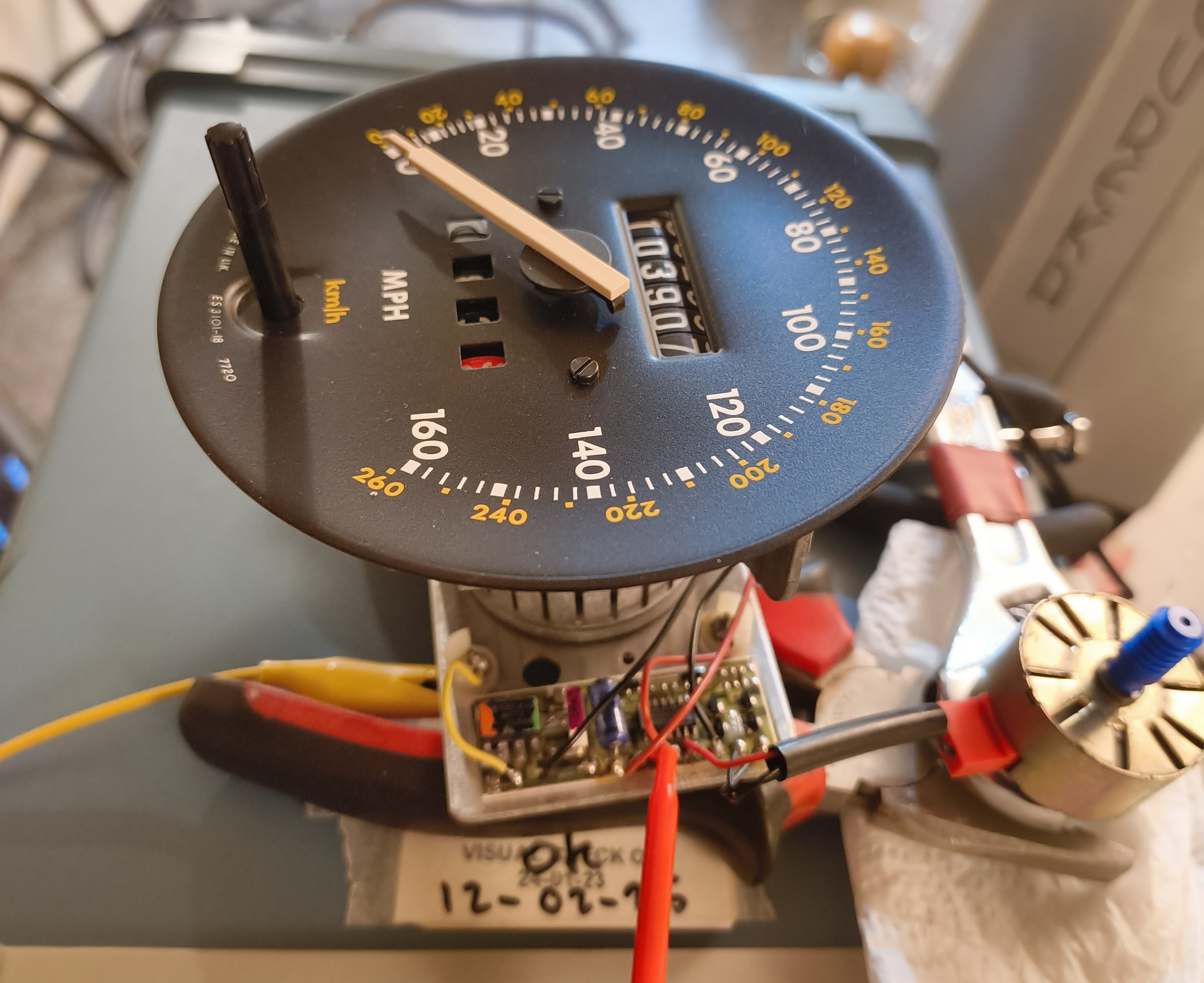
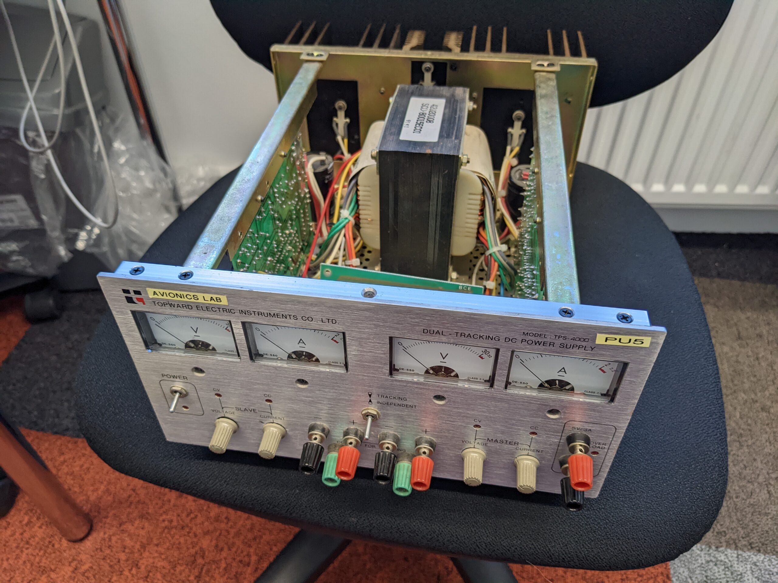
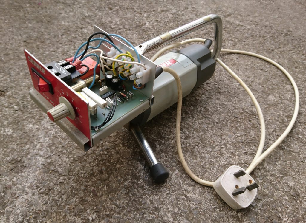
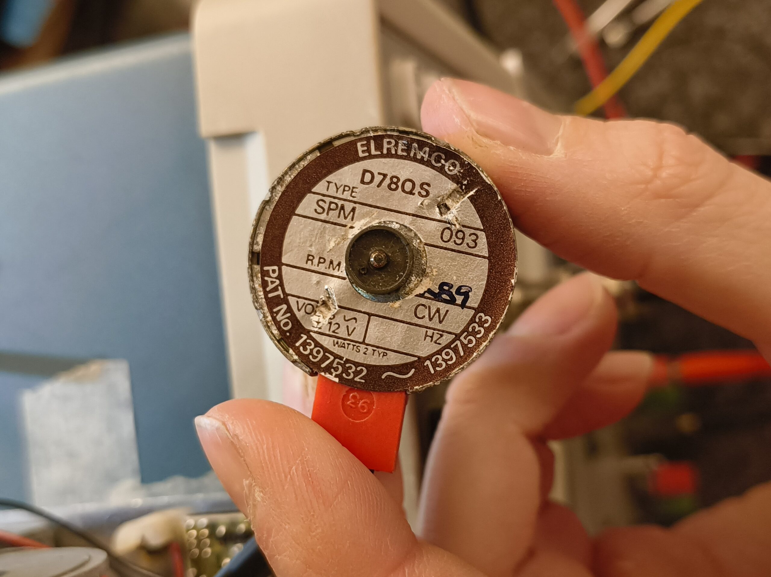
Using a bench top power supply and signal generator I managed to revive the driving motor but it was intermittent and jerky in operation. I’m not sure what type of motor it is but I flushed it with electrical switch cleaner and this improved things.
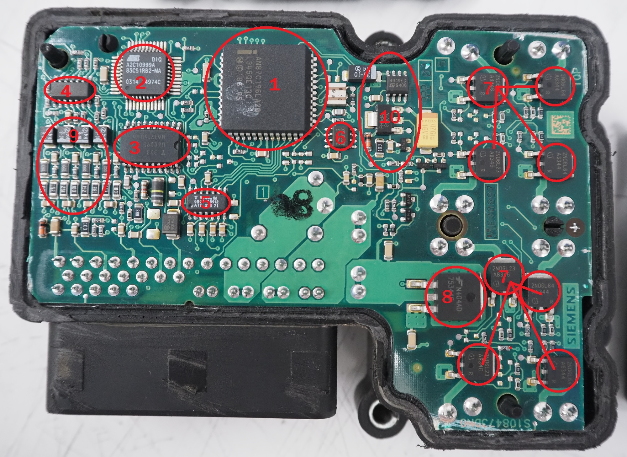
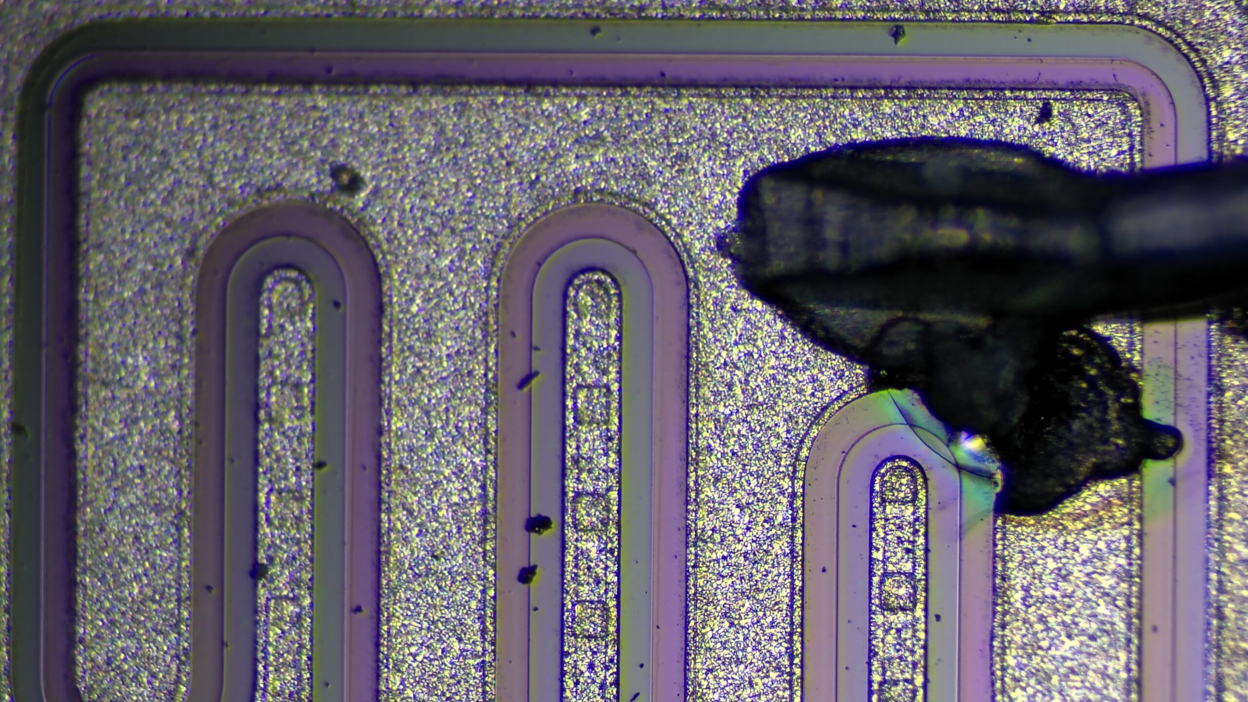
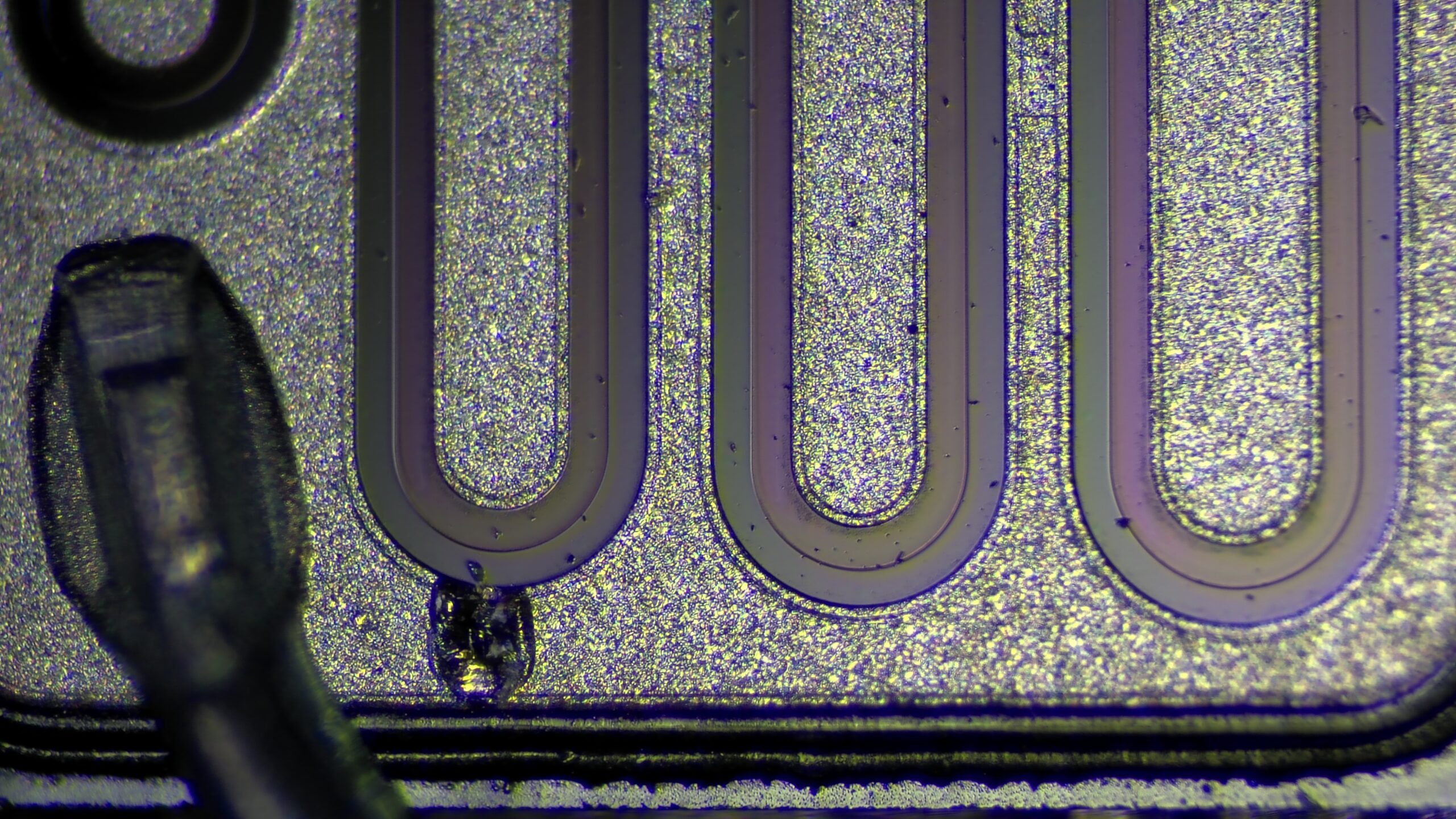
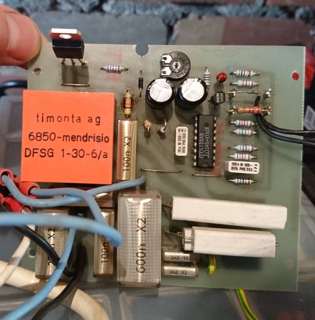
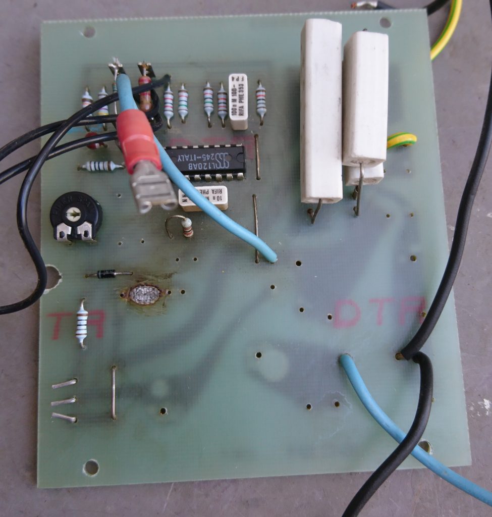
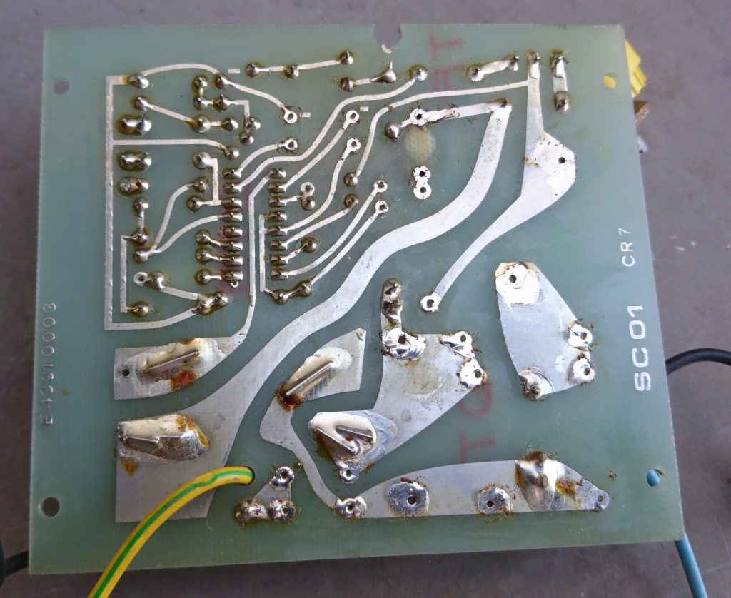
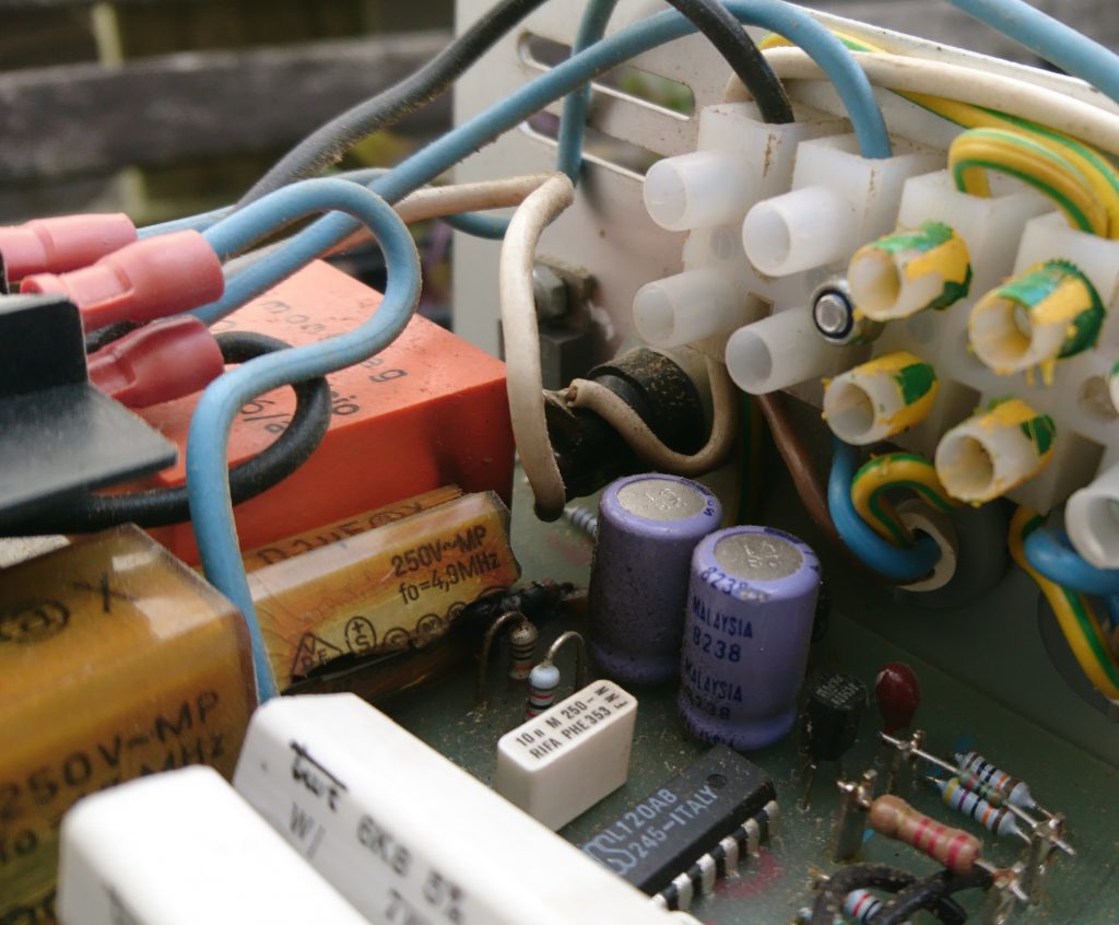
The circuit board has been discussed on other forums as it’s a similar design to the rev counter. Its a metal/ceramic substrate with thick film resistors and a mixture of surface mount and through hole mount components which I thought impressive for 1989.
The IC’s are a HEF4024B 7-stage binary counter and a TI MIC2/2 which is a custom part equivalent to a SAK215 pulse shaper IC. Other components on the board are various smt transistors including 4 of them arranged in a H-bridge configuration for driving the motor.
Here are some interesting links that discuss the speedo/odometer circuit and the similarities with the rev counter.
https://forums.jag-lovers.com/t/tachometer-rebuild/386257/12
https://forums.jag-lovers.com/t/newcomer-xjs-v12-1988-and-some-problems-start-but-no-crank/395748/73