TRW EBC 430 ABS Reverse Engineering – Part 1 PCB

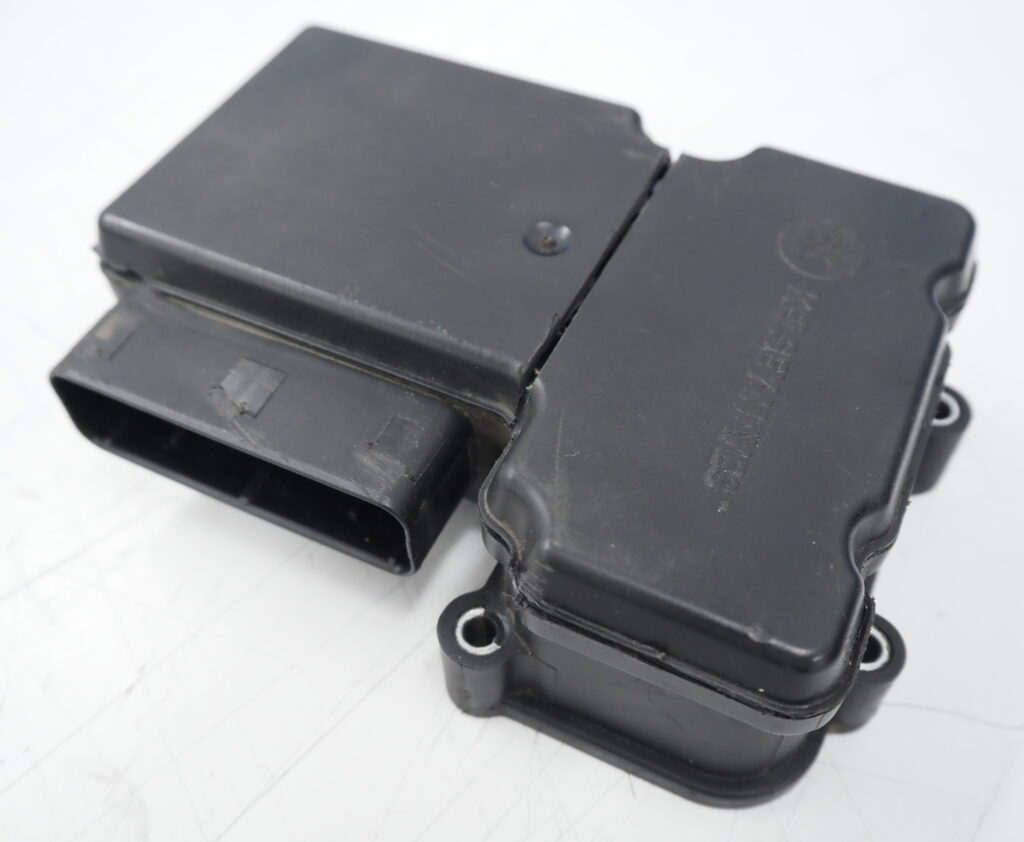
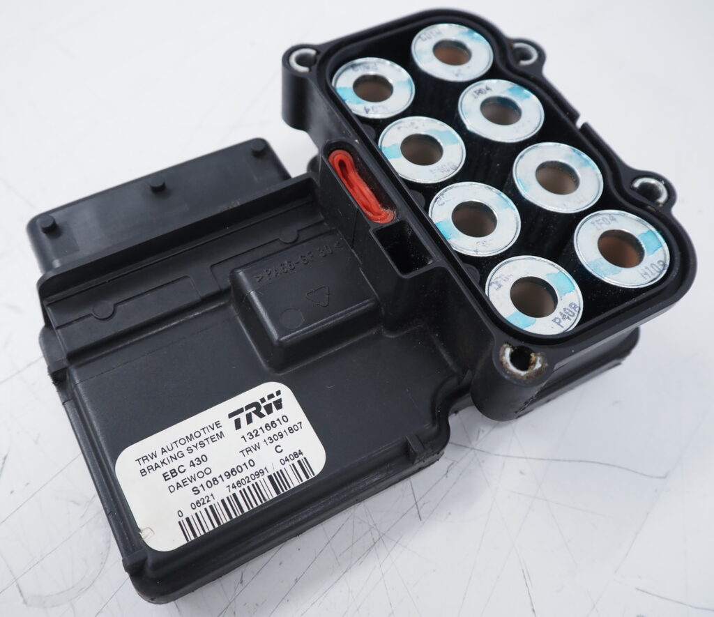
I have given myself the project of reverse engineering a TRW EBC 430 ABS unit, typically used in early 2000’s Vauxhall or GM cars.

I believe they were designed by Kelsey-Hayes and produced by TRW given the numerous ABS related patents granted to Kelsey.

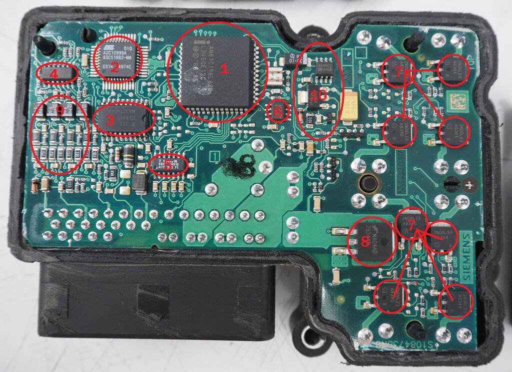
  1. Primary microcontroller – AN87C196LA which is a 16-bit Intel 80C196 variant.
  2. Secondary microcontroller – T83C51RB2 which is an 8-bit Intel 80C51 variant made by Atmel.
  3. Atmel U6809B – Failsafe IC with relay and lamp driving circuitry.
  4. ST 37041 90T316 – Judging by the surrounding components I think this is a VR sensor conditioning chip for the 4 ABS wheel speed sensors.
  5. Temic 9344.1M – Purpose unknown so far. Temic was a German semicon manufacturer who developed various automotive control modules.
  6. ST M24C01 – Serial I2C EEPROM connected to the primary MCU.
  7. Infineon 2N06L64 & 2N06L23 – N-Channel MOSFETs for driving the ABS valve solenoids.
  8. Fairchild HUF75344 – N-Channel power MOSFET for driving the ABS pump motor.
  9. Collection of diodes, resistors & capacitors – These are for filtering the VR sensor signals before processing by #4.
  10. ST L4949ED – Low drop voltage regulator for 5V output.

I’m working on a KiCad schematic for the above PCB but it’s slow going as this is a multi layer board with a solid copper ground plane on the back so it’s difficult to follow where some signals go after vias.

TPS-4000 Replacement Parts

The new parts arrived to repair the Topward TPS-4000 power supply I had diagnosed in a previous post.

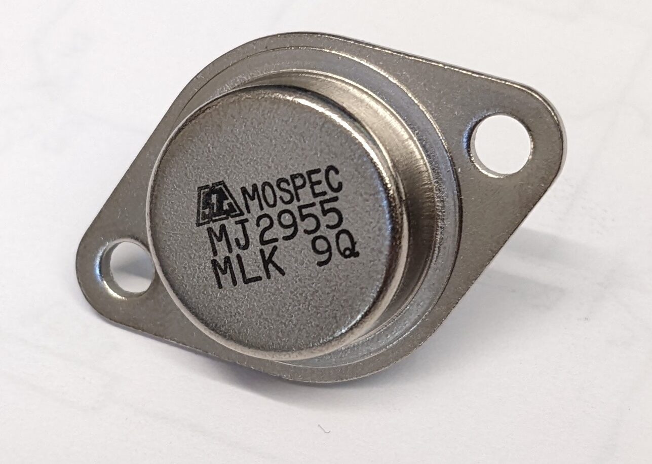
The Motorola MJ2955 was replaced with a MOSPEC branded part as originals are in short supply and popular with audio amplifier enthusiasts.

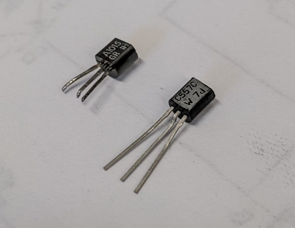
The 2SA1015GR was replaced with a BC557C as I have many of these.

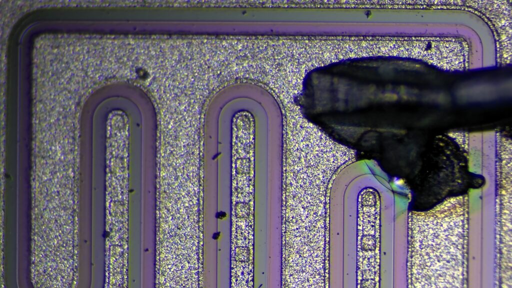
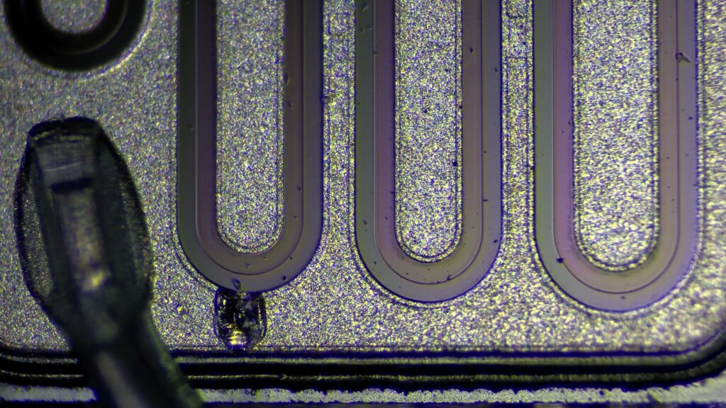
Being the inquisitive type, I decided to cut open the old power transistor to see what was inside.

Using a digital microscope I managed to capture significant damage on the silicon.

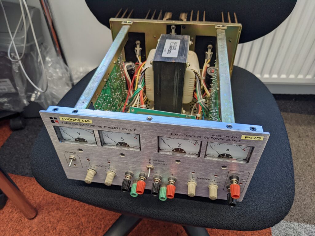
Completed power supply.

Topward TPS-4000 Power Supply Repair

The Topward TPS-4000 is a linear bench power supply with two independent adjustable outputs and a third fixed 5V output. It is this 5V output that has failed.

Original schematic (incorrect)

The original schematic seems to be missing the pass transistor and has the other transistors connected in an odd manner which suggested something might not be right.

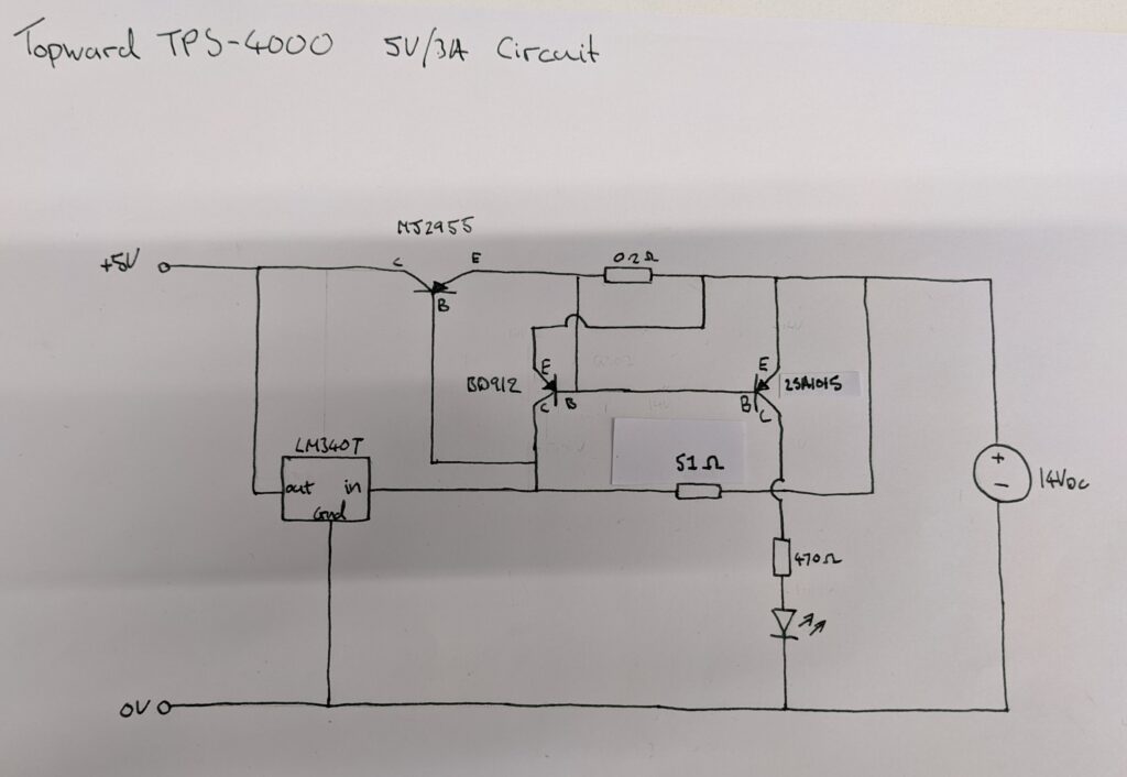
Reverse engineered schematic (correct)

The transformer/bridge rectifier/filter capacitors have omitted for clarity.

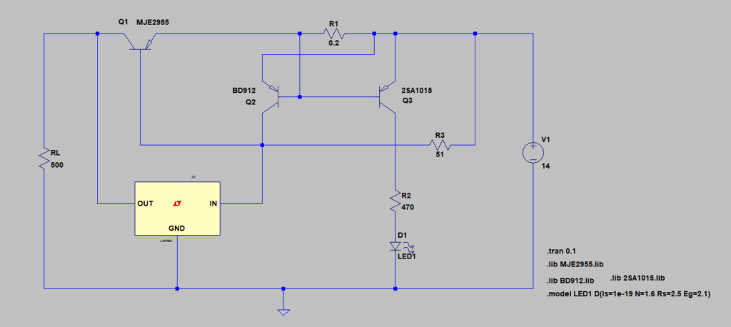
LTspice Simulation

Q2, BD912, would have originally been a 2SA699 transistor.

Failed components – Motorola MJ2955 pass transistor and 2SA1015 sense transistor.

The MJ2955 has a short circuit between the collector & emitter and the 2SA1015 has some odd junction behavior when tested under forward & reverse bias.

I’m waiting for a replacement MJ2955 and the 2SA1015 will be replaced with whatever jellybean transistor I have at hand.

New components and completion

The following pictures show the new components and the completed board.

Capacitors

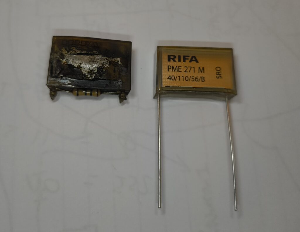
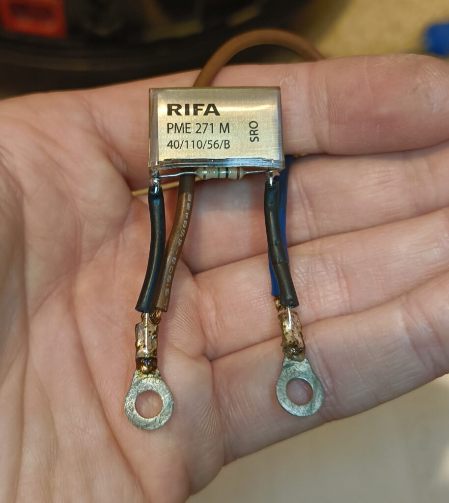
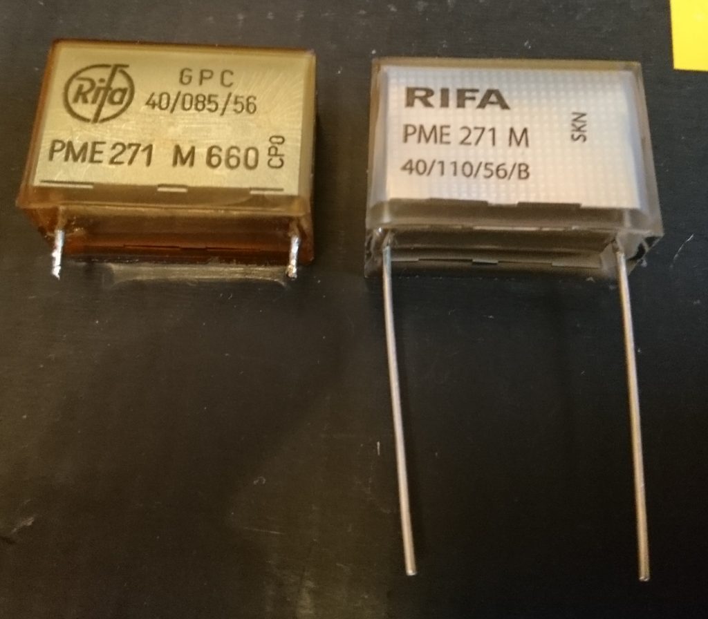
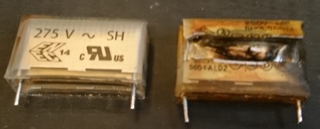
The above image shows the new and old Rifa capacitor. You can see the crazing and discolouring on the left hand side.

TRIAC

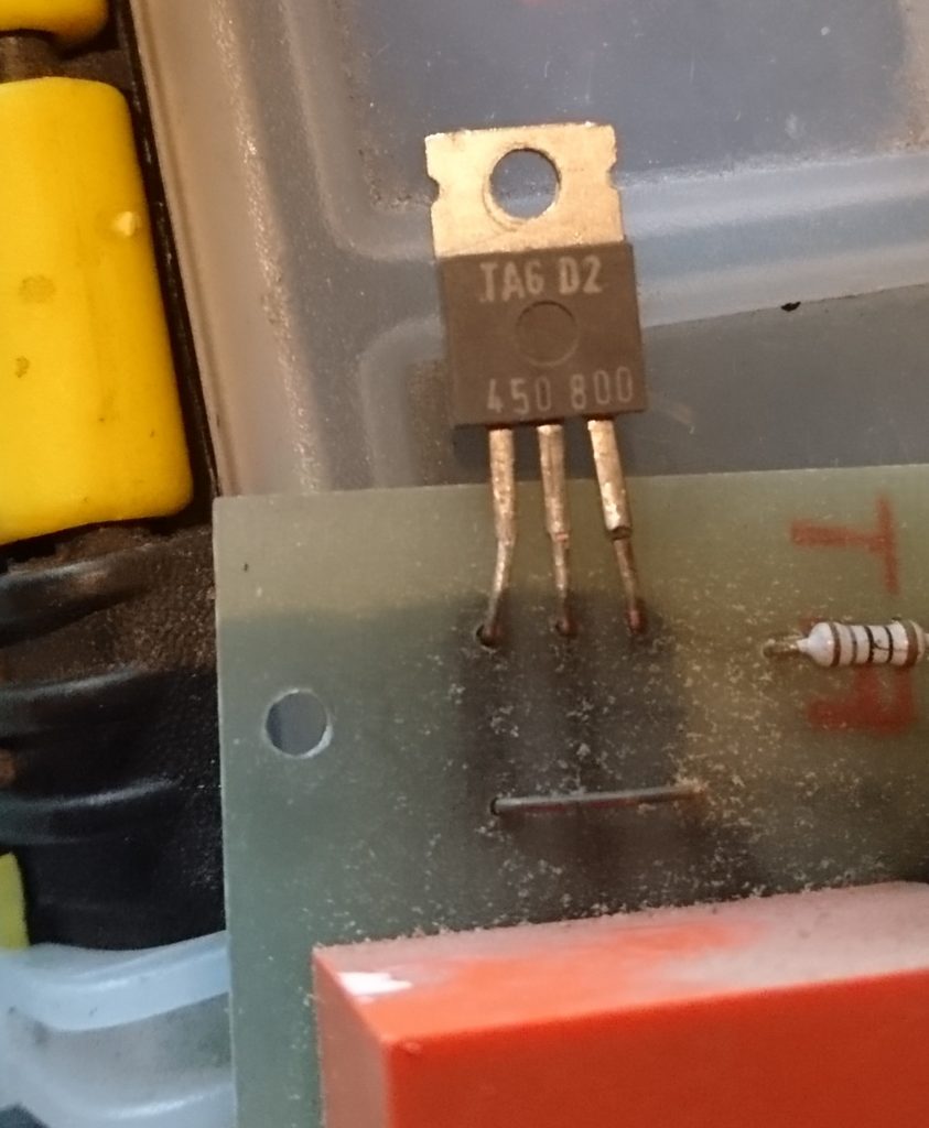
There was some difficulty in finding an alternative TRIAC. From the part numbers on the package, TAG D2 450 800 , I took a guess on the typical specifications as I could not find a vintage TAG Semiconductors parts catalogue. I used a ST BTA16-800CW with a blocking voltage of 800V and an RMS current of 16A.

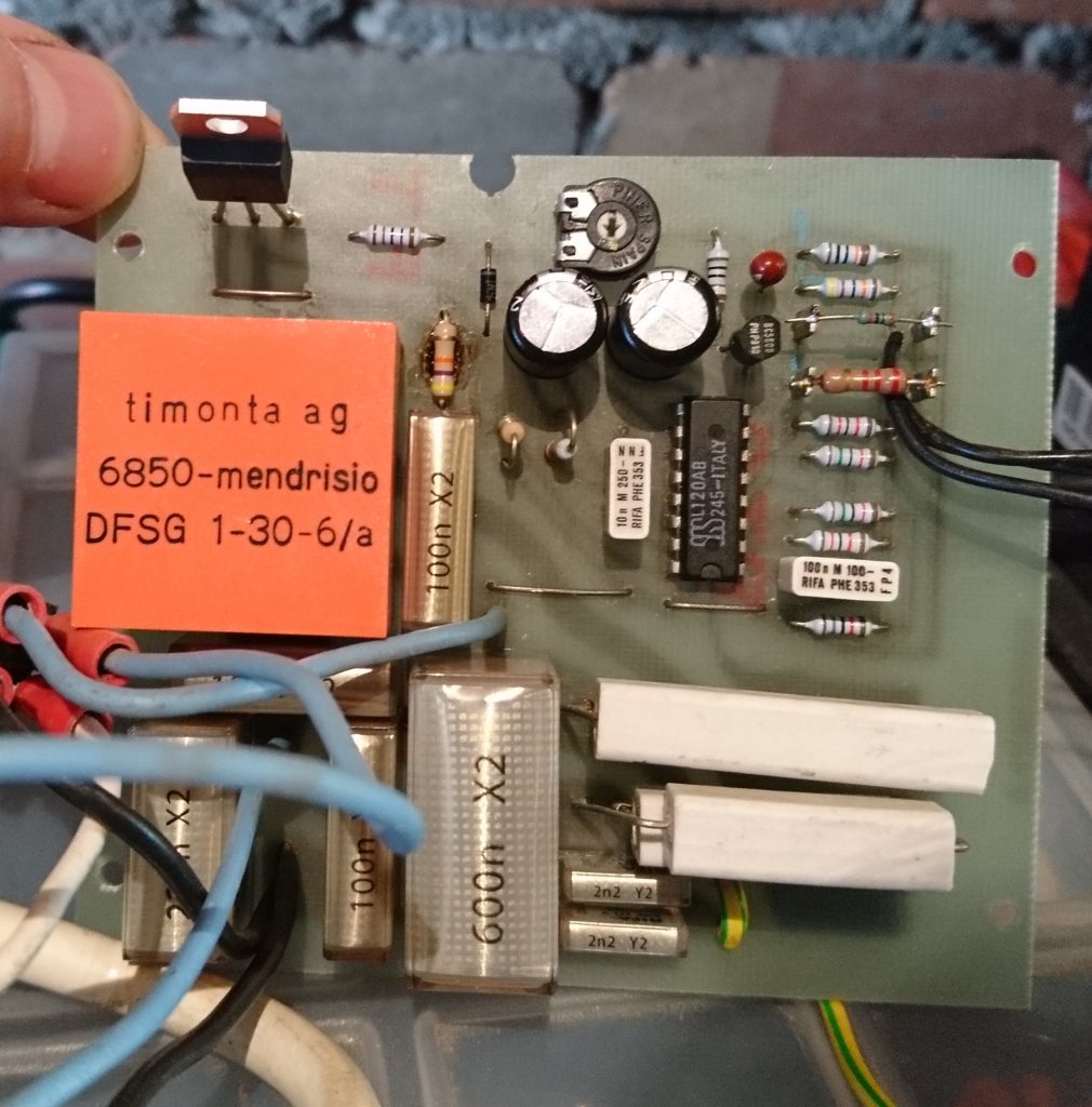
Finished PCB

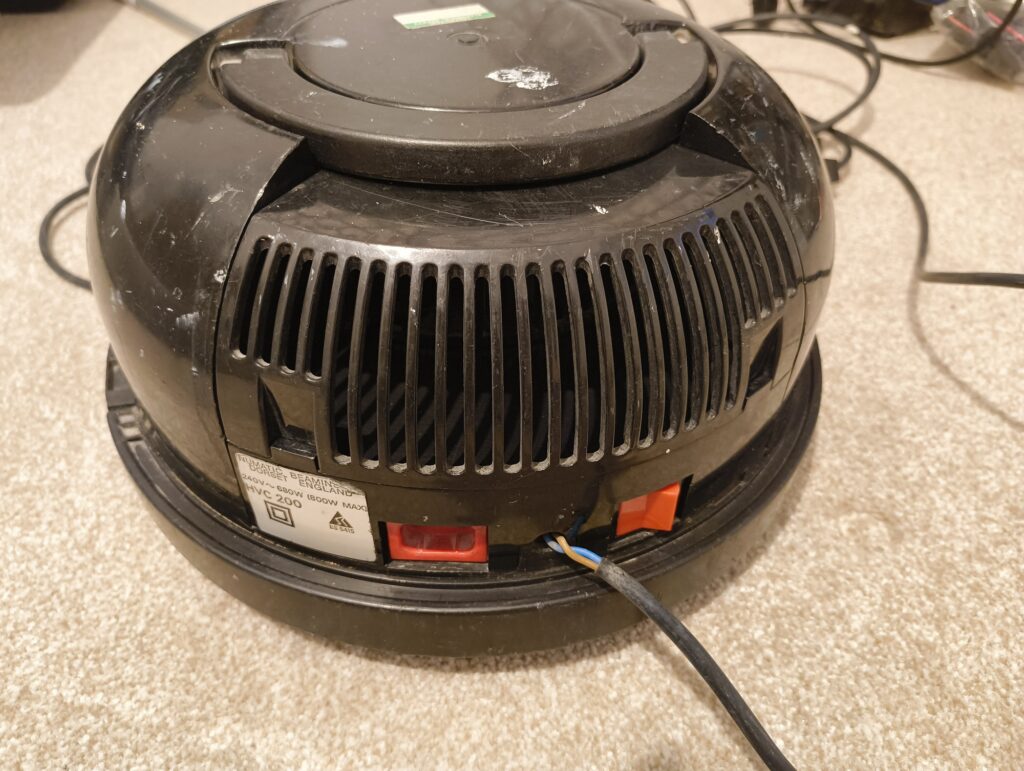
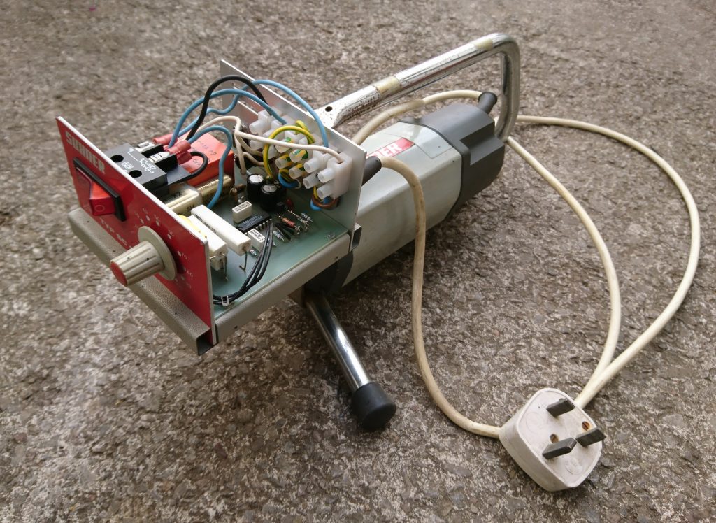
The motor is now working well unloaded and is surprisingly loud at max speed (28,000 rpm).

Watch this space for a reverse engineered circuit diagram.

PCB Cleaning

The following components were removed after inspection and shall be replaced:

2x 22pF Class Y
3x 0.1uF Class X
2x Resistors
2x 220uF Electrolytics
1x TRIAC – This was not faulty but the legs snapped on removal of the clamping bolt.
1x Inductor – Just for inspection.

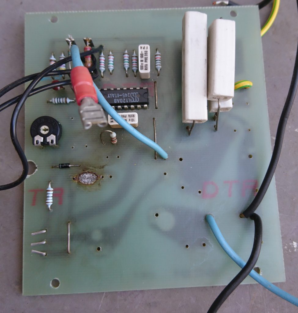
Bare PCB

The failed resistor had become quite hot and burnt the top of the PCB. I cleaned this with a fiber glass pencil and applied a couple of coats of clear nail varnish afterwards.

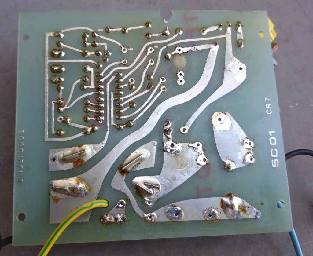
Back of PCB

The back of the PCB shows some signs of the burning but it is still intact.

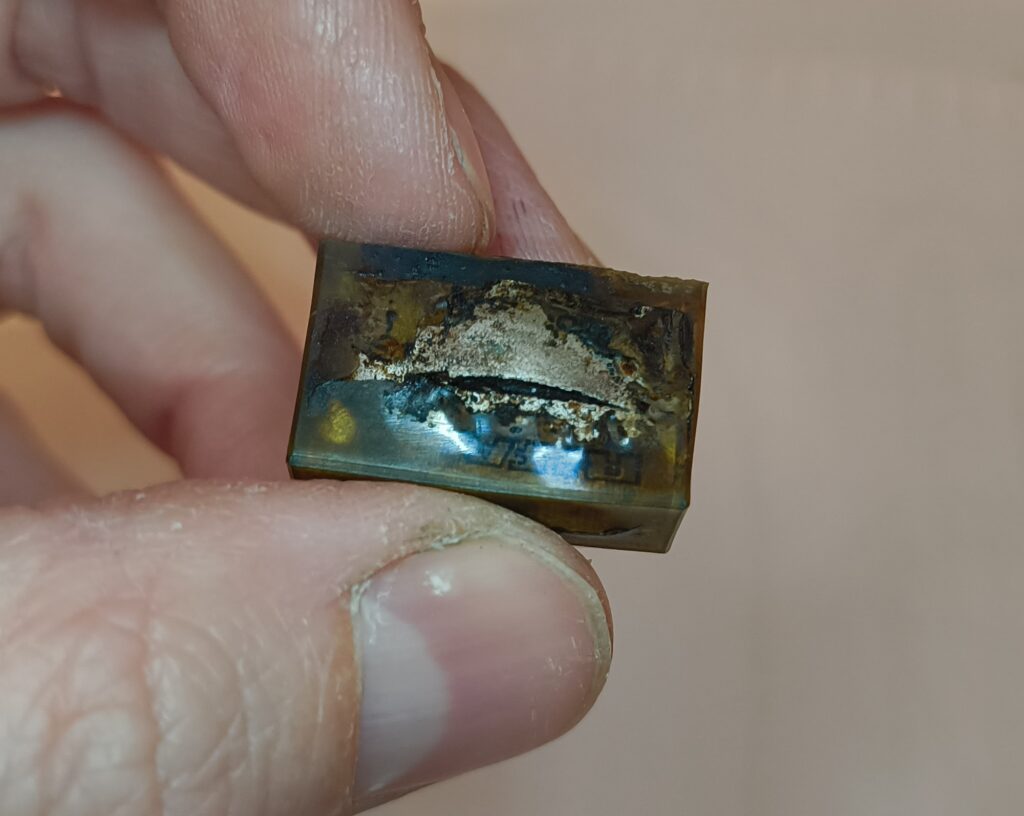
Damaged Capacitor

Above is the damaged capacitor next to it’s new replacement.

Strip Down

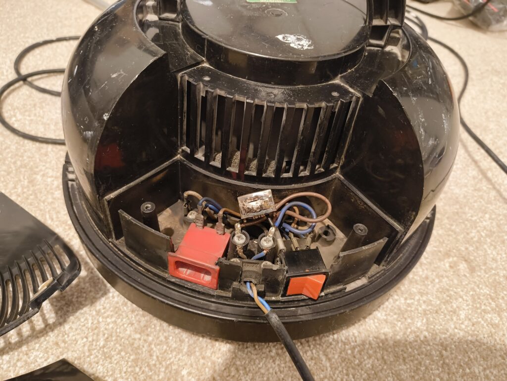
It soon became obvious once the lid was off where the magic smoke had come from and where the problem may lie.

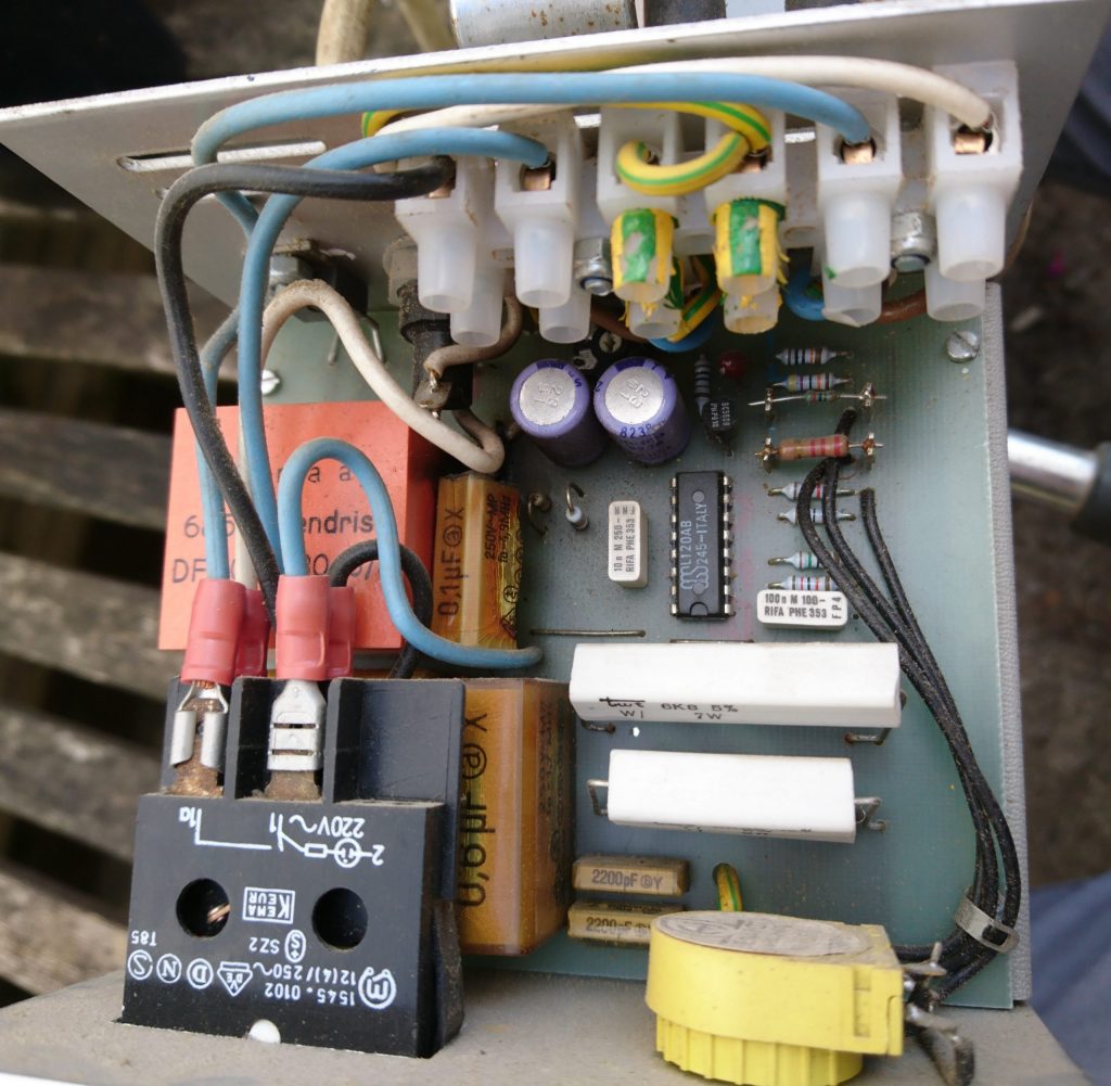
Motor controller

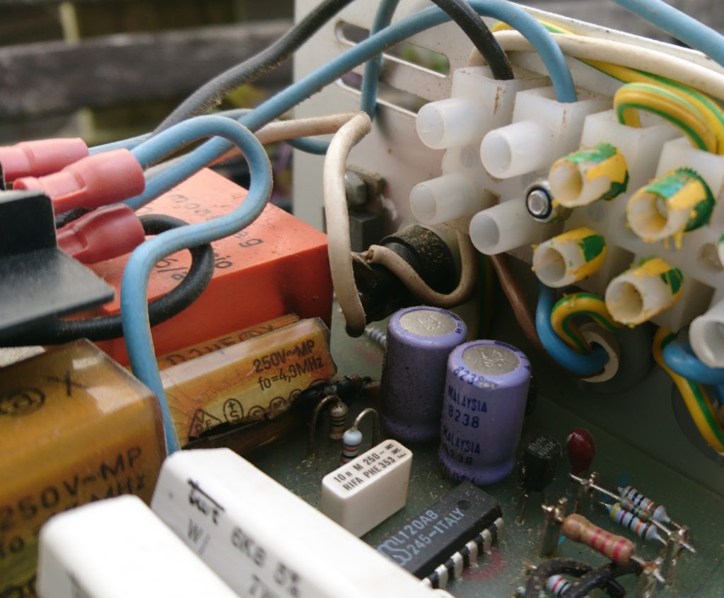
The controller is full of the dreaded ‘Rifa’ capacitors, these are paper capacitors with resin dipped casing that breaks down with heat and age allowing moisture in. Once this happens a bang soon follows.

You can see the 0.1uF capacitor in the centre of the image has split open horizontally and in the background a resistor has also burnt.